I2C Protocol Viewer
Introduction
This workspace is set up to generate I2C signals with the Protocol Analyzer's custom signal scripting tool. Through the scripting tool, the Protocol Analyzer generates a pattern correlating to the binary ASCII values of “Hello World!”. The Logic Analyzer will display the I2C transactions as hexadecimal values. The signal is generated at 40 kHz, and the Logic Analyzer is set to collect 4,096 samples at a rate of 1.02 MHz, resulting in an approximately 3 ms acquisition.
To learn more about the I2C protocol, its Wikipedia article is a good reference.
Inventory
- A Discovery Device with Digital I/O:
- An Analog Discovery (Legacy) can also be used.
- Two 1-5 KΩ Resistors (Ideally 4.7 KΩ) and a breadboard
Setup Instructions
1. Hardware Setup
Plug your Discovery device into your computer via a USB cable.
Since I2C uses open collectors on the inputs/outputs, this WorkSpace requires at least 2 resistors in order to drive the signal high with the Test and Measurement device's power supply. Please see the README text file included in the download for detailed information on how to connect the pull-up resistors.
Since I2C protocol uses open collector inputs/outputs, 2 pull-up resistors are required to drive the signal high. Optimally both resistors should be 4.7kΩ, but the protocol can handle a range of values. Pick something in the 1-5kΩ range. Connect the resistors between the power supply and the two data lines. Refer to the circuit diagram to the right.
2. Software Setup
Download and extract the WaveForms workspace from the I2C Protocol Viewer Workspace ZIP Archive (also linked in the inventory section, above).
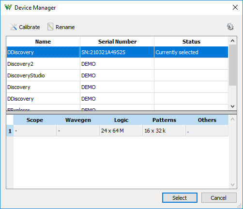
Open WaveForms. Upon launch, WaveForms will generate a prompt asking to switch to the device used with the workspace. As this is the device originally used when the workspace was created and archived, select No. Navigate to Settings → Device Manager in the menu bar at the top of the window, to check that the active device is your Discovery device.
Click the Open Workspace button on the Welcome tab. Navigate to and open the spi-protocol-viewer workspace in WaveForms.
3. Running the I2C Protocol Viewer
The workspace is ready to use.
Regardless of the device used, the voltage output for the power supplies is configured for 3.3V. To pull the I2C lines high, enable the power supplies by clicking the Run button (green arrow) on the “Supplies” tab.
Press the “Single” button in the Logic tab, then press the “Execute” button in the Protocol tab. The Logic Analyzer will display the decimal values of the ASCII codes for “Hello World!”.
Note: To view the data through the Logic Analyzer while using the Protocol Analyzer, the Protocol Analyzer was placed into debug mode, which disables the Protocol Analyzer's ability to receive data. If this workspace is used to receive data through the Protocol Analyzer, the debug button will need to be deselected.
Final Notes
This workspace is a good starting point for testing an I2C device through WaveForms. By simply modifying the contents of the ASCII array, and the Write call's address argument, different values can be sent one of several I2C slave devices on the same bus.
For more guides and example projects for your Test and Measurement device, please visit its Resource Center, which can be found through this wiki's Test and Measurement page.
For technical support, please visit the Digilent Forums.


