Using the Digital Discovery to Simulate an HD44780 Display
HD44780 compatible displays are used in a wide range of devices. They can be connected to a system using as little as 6 pins and display up to 80 alphanumerical character. The most common version uses a 2×16 character array. Display operation may be debugged using logic analyzers such as the Digital Discovery. This demo simulates the real-time operation of a display using the Digital Discovery and a computer while running a Python script.
Inventory
- A computer with a USB port to run the software
- Python 2.7 Software with Python 2.7 interpreter and Tkinter along with its dependencies
-
- 2×6 MTE Cables may be used for hardware connections
- An Arduino™
- In the example, an Arduino™ Uno™ compatible device will be used, but any other Arduino™ board capable of driving HD44780-compatible display will be suitable
- HD44780-compatible 2×16 display
- In the demonstration an LCD Keypad Shield for Arduino will be used
- Python Source Code downloaded to the computer
- Arduino Sketch Code downloaded to the computer
Step 1: Hardware Setup
1. Make sure to download the Arduino sketch linked in the Inventory section of this guide.
2. Open the sketch and upload to the Arduino UNO. The sketch will display some short content received over the serial port on the LCD. Then the LCD should be connected to the Arduino module. All the connections are standard for 4-bit operation without reading the busy flag and are described in example Arduino sketch. The circuit is as follows:
LCD RS pin to digital pin 8
LCD Enable pin to digital pin 9
LCD D4 pin to digital pin 4
LCD D5 pin to digital pin 5
LCD D6 pin to digital pin 6
LCD D7 pin to digital pin 7
Backlight control to digital pin 10
LCD R/W pin to ground
10K resistor to +5V and ground
Wiper to LCD VO pin (LCD pin 3)
3. If using a different LCD module then the Arduino code should be adjusted as required before uploading and connecting. Initialize the library by associating any needed LCD interface pin with the Arduino pin number it is connected to.
const int rs = 8, en = 9, d4 = 4, d5 = 5, d6 = 6, d7 = 7, bl = 10;
LiquidCrystal lcd(rs, en, d4, d5, d6, d7);
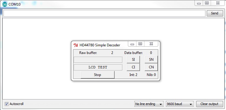
4. After resetting the device an “LCD TEST” message should appear on the display. If needed, a contrast should be adjusted. The following is how to connect the Digital Discovery to the HD44780 LCD:
Note: Ground should be connected before any other connections are made.
Digital Discovery GND to the LCD GND
Digital Discovery DIN0 to the LCD EN
Digital Discovery DIN1 to the LCD RS
Digital Discovery DIN2 to the LCD D4
Digital Discovery DIN3 to the LCD D5
Digital Discovery DIN4 to the LCD D6
Digital Discovery DIN5 to the LCD D7
Step 2: Communication
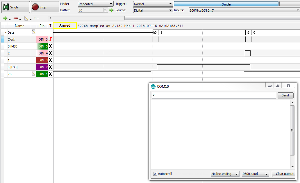
Data sent to the HD44780-compatible display can be seen using WaveForms software and the Logic Analyzer instrument. In the Logic Analyzer, add a bus with clock on rising edge of the EN signal. Next, add the RS signal as a separate signal and set trigger mode to normal with triggering on a rising edge of the EN signal. After this is set up, run the Logic Analyzer and send one letter through the serial port. The letter will appear on the LCD and in the Logic Analyzer. At this point you will be able to see the four 4-bit nibbles that were transmitted, each on the rising edge of the EN line. Nibbles are “grouped” to form an 8-bit number. The state of the RS line determines whether this 8-bit number is command RS low or data RS high. The command 0x01 (“clear display”) is sent followed by data 0x50 which is the letter “P” encoded in ASCII.
Step 3: Python-based HD44780 Emulation
Make sure to download the Python source files linked in the Inventory section of this guide.
Real-time data acquisition and analysis can be divided into steps. The multi-thread solution is a good choice. The demo has four threads:
- The GUI thread or main thread initializes equipment and is responsible for the GUI operation.
- The acquisition thread collects real-time data form Digital Discovery and puts data into a queue.
- The raw data processing thread reads data from the queue. Latching only at rising edges of EN and putting data into another queue.
- The data processing thread reads latched data from the second queue and simulates the behavior of the HD44780 display.
The data processing algorithm has some limitations:
- The full finished state machine used by the original controller is not implemented. A simplified initialization procedure is used. The command mode to data mode transition, which is a rising edge on the RS line is used to determine when the LCD is initialized. This is used to set 4-bit mode as well as other parameter's settings.
- Some commands are implemented such as Clear Screen and Set DDRAM address which sets the cursor location.
- The script is not optimized for performance.
All details about how the emulation functions are presented as comments in the script.
Step 4: Running the Example
To test the example, run the Python script. If the Raw buffer or Data buffer are filling very quickly, the sample rate should be reduced. Be aware that a too-low sample rate may not “catch” all EN pulses which can be as short as 450 ns according to specification.
# sample rate = system frequency / divider, 100 MHz / 400 = 0.25 MHz
dwf.FDwfDigitalInDividerSet(hdwf, c_int(400))
Establish a serial connection with the Arduino. You may need to reset the Arduino if the connection is already established.
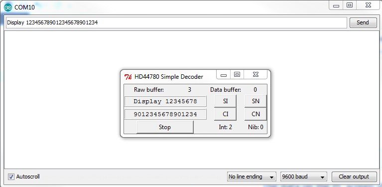
The “Int” indicator shows if the initialization was detected by the script. A value of “2” means that initialization was completed successfully and values of “0” or “1” indicate an incomplete process. If the display is already initialized when starting-up, the script user can set the SI or reset the CI initialization flag. The “Nib” indicator represents if an even number of nibbles have been received. Even is indicated with a “0” and odd with a “1”. If errors are generated, the user can also use the CN and SN buttons to manually adjust that flag. After sending some data to the Arduino through the serial port, the data is displayed on the LCD and in the user interface created by the Python script.
Next Steps
The example illustrates a simple emulator of a HD44780-compatible 16×2 display. Further development of the software can be done. For example, implementing full compatibility of the initialization process, detecting display power-cycles and auto-reset. The Digital Discovery is able to feed digital data to the computer where custom software can be used for non-standard analysis and debugging.
For more guides on how to use the Digital Discovery, return to the device's Resource Center.
For more information on WaveForms visit the WaveForms Reference Manual.
For technical support, please visit the Test and Measurement section of the Digilent Forums.


