Controlling Digital Discovery With LabVIEW

The following guide presents how to create a virtual instrument library for LabVIEW from the functions available in WaveForms SDK, how to edit the created VIs, and how to control the Digital Discovery with these VIs. Demos for spying on a digital communication protocol, for programming an AVR microcontroller, and for interfacing devices with different digital voltages can be found in the Examples section of this document.
Prerequisites
Hardware
- Jumper wires
- Pmod TMP3 - required for the Spying on I2C Communication example
- Arduino Pro Mini with 8MHz ATmega328P, or other 3V3 microcontroller (LilyPad, Arduino Fio, etc.) - required for the Programming an AVR Microcontroller example
- Pmod LVLSHFT - required for the Programming an AVR Microcontroller example if a 5V microcontroller (like Arduino UNO) is used
- Pmod USBUART - required for the Using Different Logic Voltages example
- Pmod DA1 - required for the Using Different Logic Voltages example
- red LED - required for the Using Different Logic Voltages example
- 10KΩ resistor (brown-black-orange-gold) - required for the Using Different Logic Voltages example
Software
Note: WaveForms can be installed by following the WaveForms Getting Started Guide. By installing WaveForms, WaveForms SDK will be installed, which is needed later in this guide.
Creating VIs for a Shared Library
Digital Discovery, as well as other Test and Measurement Devices, can be controlled using the functions available in WaveForms SDK. For the list and description of the available functions see C:\Program Files (x86)\Digilent\WaveFormsSDK\WaveForms SDK Reference Manual.pdf, or WaveForms SDK Reference Manual. For examples in C and Python languages see C:\Program Files (x86)\Digilent\WaveFormsSDK\samples.
To use the functions available in WaveForms SDK within LabVIEW, virtual instruments (VIs) have to be created from these functions. Follow the instructions in this guide to see, how to import the WaveForms SDK shared library in LabVIEW.
Open LabVIEW and create a new Blank VI. From the menu bar, open Tools → Import → Shared Library (.dll)…. Click Create VIs for a shared library, then click Next.
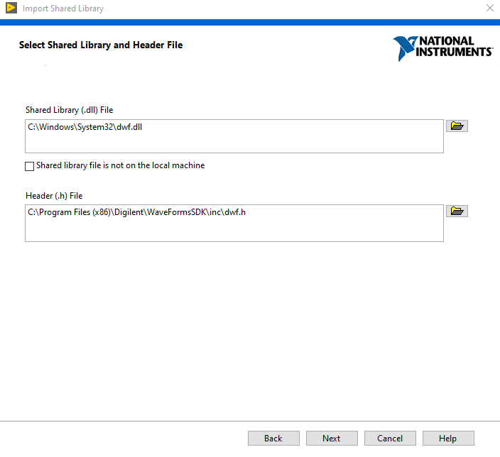
Select C:\Windows\System32\dwf.dll as the shared library and C:\Program Files (x86)\Digilent\WaveFormsSDK\inc\dwf.h as the header file, then click on Next.
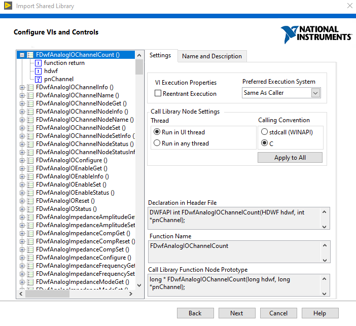
Leave the next window as it is, just click on the Next button. After the header file is parsed, a list of the available functions will appear. The wizard will create a VI for the functions selected on this list. Hit Next to continue.

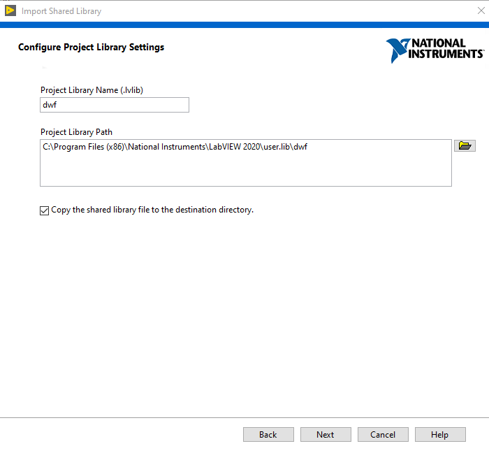
In the following window, the name and the location of the VI library can be set. By default the wizard creates the library in the LabVIEW user libraries folder, with the same name as the shared library (dwf in this case). Press Next to continue.
In the Select Error Handling Mode, select Simple Error Handling, as the error signal makes debugging easier.

Certain properties of every function can be edited in the following, but as the dwf library contains several hundred functions, it is more time efficient to leave every function with the default settings and edit just certain functions before using them (this is discussed in the Editing Generated VIs section). After displaying a Generation Summary, the wizard starts to generate the VIs from the shared library functions. The process takes time, so be patient.
When the Generation Process is finished, the VI library is ready to use. However, in the case of certain functions, an edit to the generated VI is necessary.
Editing Generated VIs
In the case of some functions, it might be needed to make some changes to the generated VI, before using it. To do this, open LabVIEW, create a new Blank VI, then open the Block Diagram (with Ctrl+E, or from the menu bar under the Window menu). Right click on the blank diagram, and select User Libraries → dwf → VIs, then place on the block diagram the function which you want to use. In this example the F Dwf Digital I2c Read VI will be edited (you can use the search button to find a specific function).
Double click a VI to open its content, then open the Block Diagram (with Ctrl+E, or from the menu bar under the Window menu). You will see the definition of the function, and below it, one single block with controls at the input (left) side and indicators at the output (right) side.
You can modify your function from here, as you wish. In this demo the data type of the read data buffer will be changed.
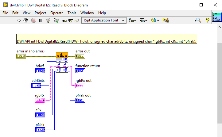
Double click on the block (orange rectangle, with some black pattern on it), then select Parameters in the window that opens.

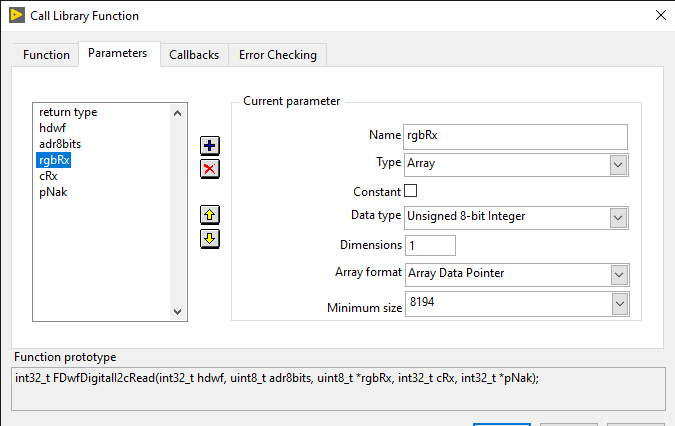
In the WaveForms SDK Reference Manual search for the chosen function. In this case it is the FDwfDigitalI2cRead function. The function description shows that the buffer for the read data is rgbRx of type unsigned char*.

In LabVIEW select rgbRx from the Parameters window. The function can be used more easily if this parameter is not a string, but an array of characters. At the Type drop-down select Array and at the Data type drop-down select Unsigned 8-bit Integer (it is the same size as unsigned char). Accept the changes.
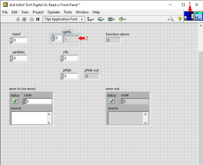
On the block diagram, delete the control and indicator elements connected to the selected parameter. Delete the wires connected to them as well. Hover the mouse over the rgbRx parameter on the output (right) side of the block, then right click it and select create indicator. As the selected parameter is a buffer for the read data, creating a control element for it is not necessary. Press Ctrl+U to organize the diagram.

Double click on the created indicator to highlight it on the Front Panel. In the upper right corner of the Front Panel click on an empty terminal (white square) on the terminal selector (1), then click on the rgbRx indicator field (2).
Save the changes and close the Front Panel. It can be seen that an output terminal appeared on the block of the edited VI, with the name rgbRx of type Unsigned 8-bit Integer Array.
Examples
You can try the examples provided in this guide, or you can create your own examples using the created VI library.
- Spying on I2C Communication
-
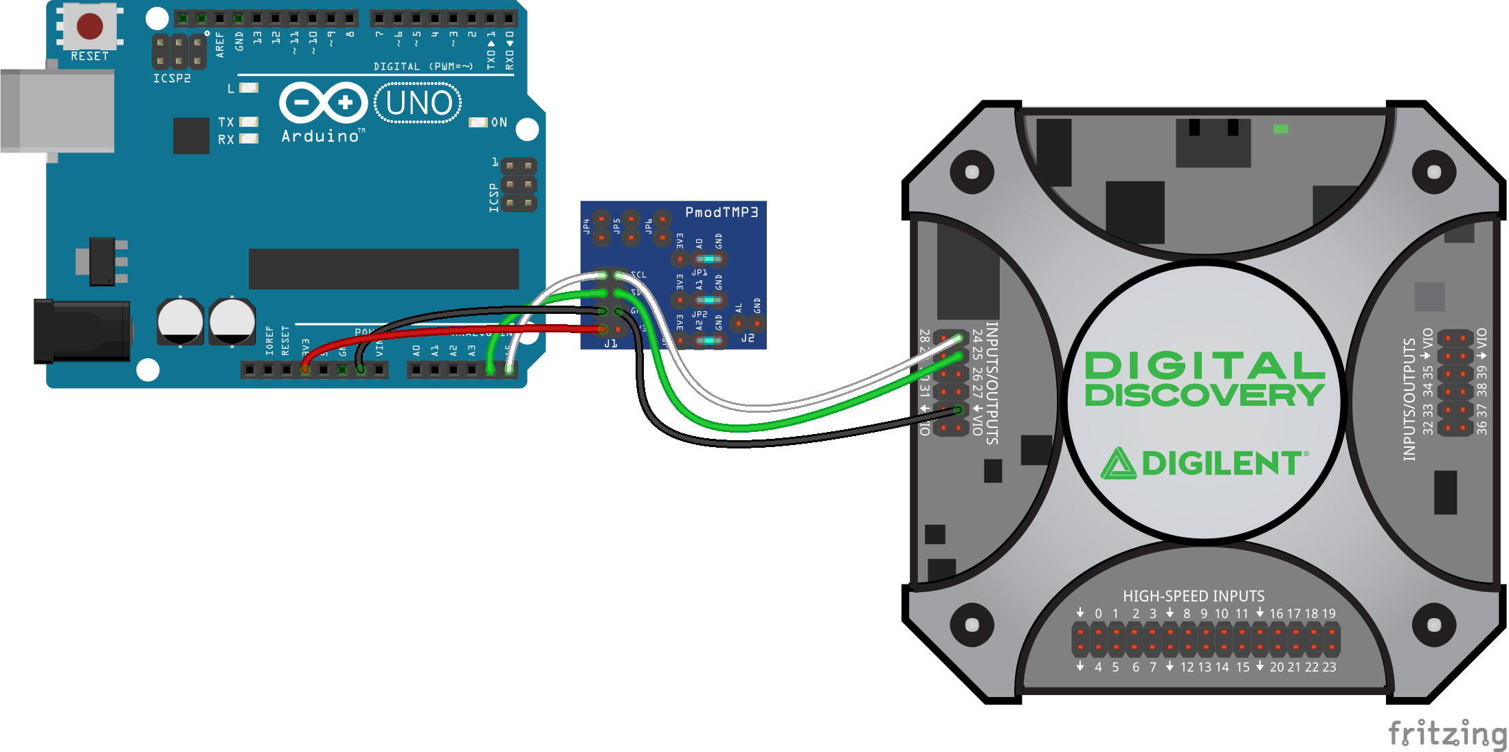
In the following project Arduino UNO and Pmod TMP3 are used to measure the ambient temperature and to send it to a PC. Digital Discovery is used to spy on this communication, to receive the data and to display the temperature on a LabVIEW user interface.
Preparations
As this guide focuses on controlling Digital Discovery, interfacing the Arduino UNO with Pmod TMP3 is not presented in detail. For a detailed guide about programming an Arduino to measure the temperature with Pmod TMP3, see: Using the Pmod TMP3 with Arduino UNO. Follow this guide before continuing.
Hardware Setup
To spy on the communication between the Arduino UNO and the Pmod TMP3, Digital Discovery must have a common reference (ground) with these devices, and the serial data and serial clock lines have to be connected to the Digital Discovery's DIO lines, like in the picture to the right.
Software Setup
A LabVIEW Virtual Instrument consists of two parts: the Front Panel and the Block Diagram. The Front Panel contains all controls and indicators for data input and output and serves as a user interface when the program is running. The Block Diagram contains the blocks which are present on the Front Panel, as well as other blocks which are necessary for information processing and the connections between these blocks. One can add a new block to both windows by right clicking on a blank space in the corresponding window and selecting the required block from a library. Blocks already present in the window can be modified by right clicking on the respective block. In the following the Front Panel and the Block Diagram of this example will be presented.
Download and unzip the provided example file spy_tmp3.zip then double click on it to open it with LabVIEW Community. All the functions used in the example can be used in your own VI, play around and see what else you can create.
Note: For this VI to work, the dwf VI library is necessary (see: Creating VIs for a Shared Library).
Front Panel
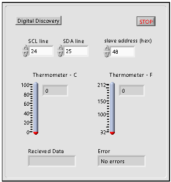
The Front Panel contains the Stop button, which stops the program and closes Digital Discovery to make it available for other software, as well as three control elements: input fields for defining Digital Discovery DIO lines connected to the Arduino's I2C data and clock lines and an input field for entering the I2C slave address in hexadecimal format.
Below the control elements, two thermometers are placed to show the measured temperature in degrees, in Celsius and Fahrenheit. At the bottom are two text fields: one for indicating errors, and one for displaying the received data in hexadecimal format.
Block Diagram
In this example, the Block Diagram has three main parts. The first part is responsible for configuring the Digital Discovery. The first function (F Dwf Device Close All) closes all Digilent Test and Measurement instruments to make them available for this program. The function F Dwf Device Open with the input parameter -1 opens the first available device and sends the device handler for all the other functions in this VI.
The I2C clock frequency is set to 100 KHz, then the SCL and SDA pins are defined. The DIO pins of the Digital Discovery are numbered from 24 (in default mode), so 24 has to be subtracted from the inputted numbers, 24 becoming DIO 0 and 25 becoming DIO 1. The F Dwf Digital I2c Clear function checks the pull-ups on the serial data and clock lines and returns 0 if there is an error at the connection.
Continuous reception of data is only started if there was no error at the pull-up check. If the check fails, an error message is displayed and data reception is not started.
At every iteration of a while loop, 2 bytes of data are received from the address defined on the front panel. The function F Dwf Digital I2c Read is edited, so the read data buffer is outputted to an Unsigned 8-bit Integer Array and not to a String (see: Editing Generated VIs).
The two received bytes are concatenated and shifted to the right with four bits, then raw data is converted to degrees Celsius and Fahrenheit and displayed on the Front Panel with the help of the thermometers. The received bytes are converted to hexadecimal strings, then concatenated with “0x” and displayed in the respective field on the Front Panel.
The loop is exited if there is an error, or when the Stop button is pressed.
When the loop is exited, the digital in- and out instrument parameters are reset, then the device is closed to make it available for other software. Errors are handled, if there were any.
Testing
After the devices are connected and the used DIO lines and slave address specified, the program can be started with the Run button on the Front Panel. The thermometers show the same temperature, as the one measured by the Arduino, while in the respective text field received raw data can be seen in hexadecimal format.

- Programming an AVR Microcontroller
-
In the following project Digital Discovery is used to program an AVR microcontroller (Arduino Pro Mini in this case). To control the programming parameters and to receive feedback about the state of the devices, a LabVIEW user interface is used.
Note: This programming method overwrites Arduino bootloaders, which means that the microcontrollers can't then be programmed from USB. To re-enable this feature after finishing the testing of this example, burn the bootloader to the used microcontroller following this guide: ArduinoISP.
Preparations
As this guide focuses on controlling the Digital Discovery, creating an Arduino project is not presented in detail. For a detailed guide about creating a project for Arduino, check Arduino - Tutorials. For this guide, the built in Blink example will be used, which can be found in the Examples → Basics → Blink menu. Save this project in a chosen location, or use a project of your choosing.
Hardware Setup
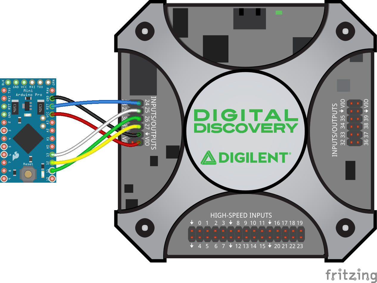
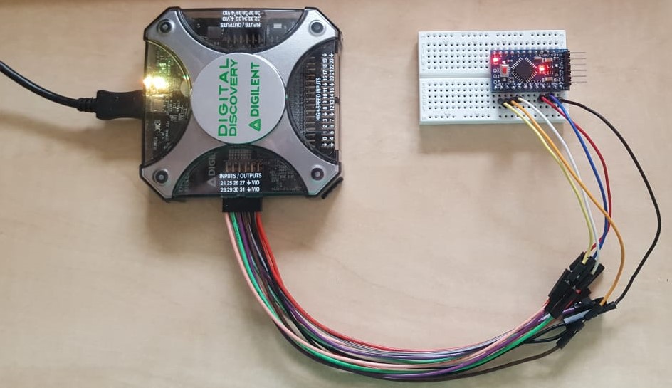
To program the microcontroller, the SPI interface will be used, but the Chip Select signal will be connected to the Reset pin of the microcontroller. The MCU also needs to be powered, for which a VIO line of the Digital Discovery will be used, as in the picture to the right.
- Using a 5V microcontroller
-
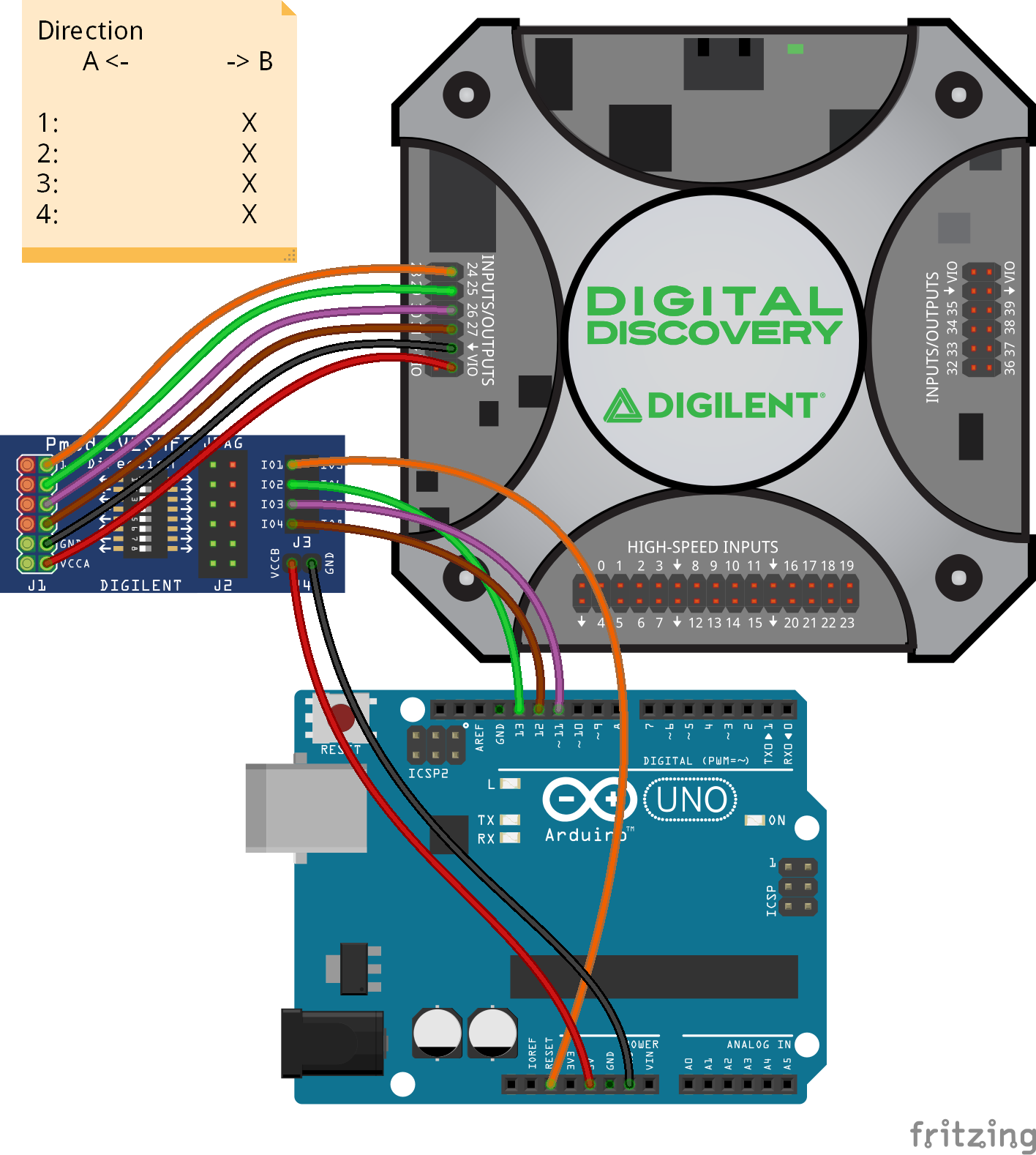
As the Digital Discovery's maximum output voltage is 3.3V, a logic level converter must be used to program a 5V MCU. To translate the signals coming from the Digital Discovery, the Pmod LVLSHFT is used. If the microcontroller is connected to the B side of the level converter and the Digital Discovery to the A side, the direction switches of the channels used must be switched to the B side.
After the program is uploaded to the MCU, either the VI has to be stopped or the connections between the Pmod LVLSHFT and the MCU must be removed in order to start running the uploaded program.
The microcontroller must be powered from an external power source, for example, a USB cable in the case of Arduino UNO.
Software Setup
A LabVIEW Virtual Instrument consists of two parts: the Front Panel and the Block Diagram. The Front Panel contains all controls and indicators for data in- and output and serves as a user interface when the program is running. The Block Diagram contains the blocks which are present on the Front Panel, in addition to other blocks necessary for information processing, and the connections between these blocks. One can add a new block to both windows by right clicking on a blank space in the corresponding window and selecting the required block from a library. Blocks already present in the window can be modified by right clicking on the respective block. The Front Panel and the Block Diagram of this example will be presented.
Download and unzip the provided example file (avr_programmer.zip) then double click on the main VI (program_AVR.vi) to open it with LabVIEW Community. All the functions and subVIs used in the example can be used in your own VI, play around and see what else you can create.
Note: For this VI to work, the dwf VI library is necessary (see: Creating VIs for a Shared Library).
Front Panel
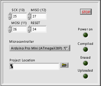
The Front Panel contains the Stop button, which stops the program and closes Digital Discovery to make it available for other software, four input fields for defining Digital Discovery DIO lines connected to the microcontroller's SPI data, reset, and clock lines, as well as a drop-down list for selecting the microcontroller type, and an input field for selecting the Arduino project.
To the right of these, four virtual LEDs are placed, for indicating the state of the MCU: the Power on LED turns on when the MCU is powered, the Compiled LED turns on once the project has been compiled, the Erased LED turns on after the flash memory and the EEPROM of the MCU are deleted, and the Uploaded LED turns on after the compiled program is copied in the flash memory.
Block Diagram
The main VI (program_AVR.vi) contains several parts separated by decorative and functional structures, as well as multiple subVIs. In the following, these will be presented.
The first block contains functions for first closing every opened Test and Measurement device, then opening the first available device. Following that, the digital voltage is configured to be 3.3V, then power on the VIO pins is turned on. For more information on these functions, see: WaveForms SDK Reference Manual (Legacy). The power on indicator LED is turned on after the functions are executed.
The next block compiles the project, using the Arduino IDE compiler from command line, with the System Exec VI. The command line is started using the default installation directory for Arduino IDE. Using the default directory in Windows, this is “C:\Program Files (x86)\Arduino”. If you changed the installation directory when you installed the IDE this will be different. Choosing the microcontroller on the front panel results in passing the correct board definition as a command line argument to a block, which concatenates strings to get the command. The project path is used to locate the project and to define the project name.
After concatenation the command to be executed is: “cmd /c arduino –pref build.path=path\to\project\build –board arduino:avr:board:definition –verify –preserve-temp-files path\to\project\project_name.ino”. This command compiles the selected project for the selected microcontroller, keeping the temporary files in the build folder inside the project. For more information, see the Arduino Manual Page.
The Compiled virtual LED is turned on after the command is executed. The flash memory size and page size of the microcontroller and the path to the compiled HEX file are also set in this block.
The next parts are responsible for initializing SPI communication on the selected lines, with a clock frequency of 1MHz, then erasing the memory of the microcontroller. The respective indicator LED is turned on after this step.
After 100ms, the content of the HEX file is read, and the data to be written in the flash memory of the MCU is put into an array. The program offset is also extracted from the file. The next block (AVR_write.vi) gets the flash memory size, the flash page size, the program offset, and the data from the previous block as parameters, and saves this data in the flash memory of the MCU.
The function F Dwf Digital Spi Write, from the dwf VI libary, used in the AVR_write subVI, has to be edited: The type of parameter rgTX needs to be changed from String to an Array of Unsigned 8-bit Integers. A terminal should be also connected to the control field of this parameter. For more information see Editing Generated VIs.
After the Uploaded indicator is turned on, the digital in- and out instruments of the Digital Discovery are reset, to ensure the proper functioning of the MCU.
A while loop ensures that the MCU remains powered until the Stop button is pressed in the front panel. When the loop is exited, the power supply and the indicator LEDs are turned off, then the device is closed to make it available for other software. Errors are also handled here, if there were any.
SPI_init.vi
This subVI uses the WaveForms SDK functions from the dwf VI library to initialize SPI communication with a connected Test and Measurement device. After the clock frequency is set, the clock and data lines (MISO and MOSI) are specified. In default mode, the pins of the Digital Discovery are numbered from DIO 24, so 24 has to be subtracted from the inputted numbers.
The idle state of the data lines is set (default is high impedance state), then the SPI mode (0) and the endianness (MSB first) are set. The chip select line is specified and pulled up. Finally a dummy write command is issued while keeping the chip select high, to initialize the serial clock.
AVR_erase.vi
This subVI uses the WaveForms SDK functions from the dwf VI library to pull the chip select line (connected to the RESET pin of the MCU) low, then send the command for the MCU to enter into programming mode (0xAC530000) and to erase the flash memory and EEPROM (0xAC800000).
HEX_parse.vi
This subVI opens the HEX file created by the compiler, then loads its content to a string. From the first line of this string, the program offset is extracted. From every other line, the start code, the byte count, and the address are removed (first 7 bytes), then it is checked whether the current line contains data or not. If it contains data, this data and the checksum are concatenated to the string of previously saved data, then each two consecutive bytes are converted into a number, creating an array of numbers from the string containing the data.
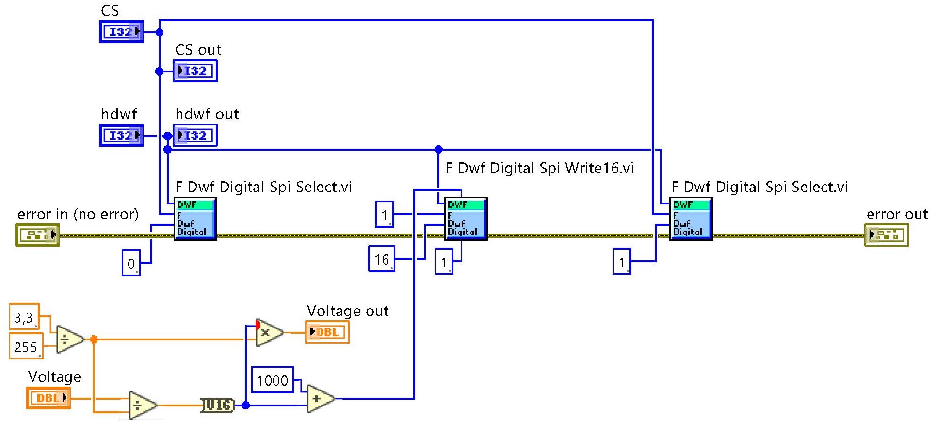
AVR_write.vi
In this subVI, data received is saved in the previously erased flash memory of the microcontroller. As a first step, the number of addresses to write is calculated. A for loop, repeated for every flash page, calculates the number of bytes in the current page, then creates an array from the load program memory commands, the addresses and the data: 0x4000-address-data for low byte, 0x4800-address-data for high byte (see the ATmega328PB datasheet).
Whether all the values on the page are equal to 0xFF is also checked. If yes, the page is not saved. If no, data is transferred through the SPI interface, then the write program memory page command (0x4C-page_address) is issued. When the page is saved, the next page follows. The loop is exited after all the pages are full, or all data is saved. The chip select line (connected to the RESET pin of the MCU) is pulled high, so the MCU exits the programming mode and starts to operate normally.
Note: The type of the parameter rgTX, in the function F Dwf Digital Spi Write, is changed from String to an Array of Unsigned 8-bit Integers.
Testing
After the devices are connected to the DIO lines and the microcontroller type and the project location are specified, the program can be started with the Run button on the Front Panel. The virtual LEDs on the Front Panel will light up in order, as the programming stages are finished.
After the MCU is programmed, the Digital Discovery continues to supply power for it, until the Stop button is pressed. In the case of this example, the blinking of the built in LED on the Arduino Pro Mini can be observed.
Note: If a 5V MCU and the Pmod LVLSHFT are used, after the program is uploaded, either the VI has to be stopped or the MCU must be disconnected from the Pmod LVLSHFT, to start normal operation.
- Using Different Logic Voltages
-
In the following project the Digital Discovery is used to interface a 3.3V USB to UART converter (Pmod USBUART) with a microcontroller (ATmega328P) running in low power mode, supplied with a voltage set by the user.
Note: Using the microcontroller in low power mode overwrites Arduino bootloaders, which means that the microcontrollers can't then be programmed from USB. To re-enable this feature after finishing the testing of this example, burn the bootloader to the used microcontroller following this guide: ArduinoISP.
Preparations
In this example, the ATmega328P microcontroller, the controlling unit of the Arduino UNO, is used. While the minimum voltage for supplying the Arduino UNO is 5V, the MCU will be used with a supply voltage as low as 1.8V, lowering the consumption of the device from above 10mA to below 0.1-0.2mA. To achieve this, the clock frequency of the microcontroller is reduced from 16MHz to 1MHz, which is in the safe operating area of the microprocessor, when operated from 1.8V (check the datasheet for more details).
To change the settings of the MCU, its fuses have to be reprogrammed. To lower the clock frequency, the 8MHz internal oscillator will be used, instead of the 16MHz external crystal, and it will be divided by eight. The brown-out detector (BOD) of the chip must be turned off as well. The calibration of the internal oscillator is beyond the scope of this example, but because it won't be used anything timing-specific in the code of the MCU, it can be left as it is.
Download and extract the variable_logic_voltage.zip file, then in the LED_control directory, open the sketch (the .ino file) with the Arduino IDE. In the Sketch menu, hit Export compiled binary, or use the exported binary file (the .hex file) in the following.
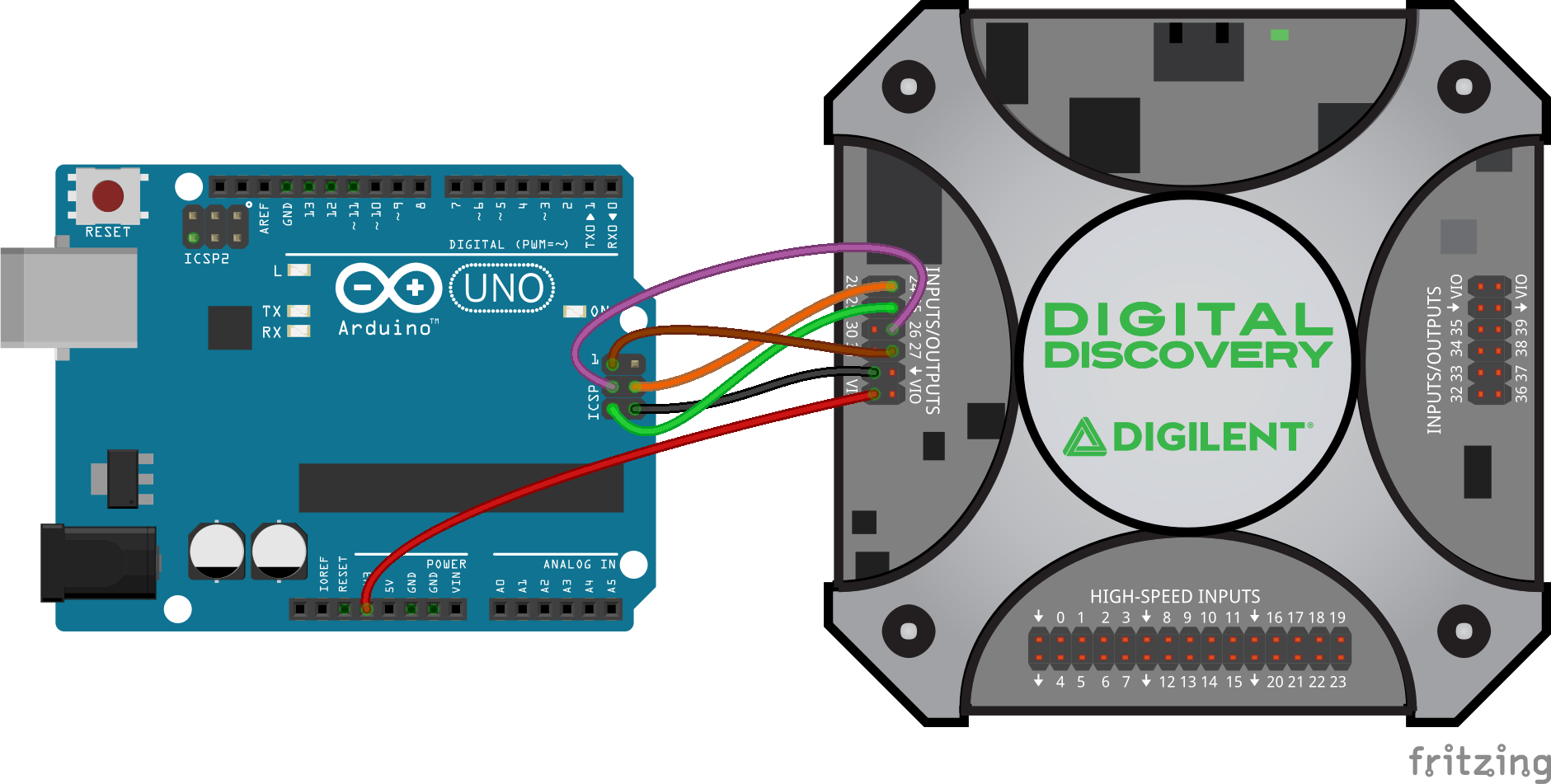
Connect the Arduino UNO to the Digital Discovery, as in the image to the right.
As the ArduinoIDE doesn't provide a method for writing the fuses, instead WaveForms will be used. Connect the Digital Discovery to the PC and open WaveForms. Open and start the Supplies instrument. Open the Protocol instrument and select the AVR tab.
Hit Auto Rate to detect the communication frequency. Press the Identify Chip button. You should see ATmega328P as the Chip, and h1E950F as the Signature.
In the Flash tab, select the compiled binary file, then write it to the flash memory. In the Fuse Lock Calibration write hFF in the Extended textbox and modify the respective fuse with the Write button. Write hD9 in the High textbox and modify the fuse. Finally write h62 in the Low text box and modify the last fuse.
You can stop the Supplies and close WaveForms. As in the following only the ATmega328P microcontroller will be used, not the whole Arduino board, you can extract the chip from its socket. Be careful, not to bend its legs when taking it out. The use of a small screwdriver is recommended.
Hardware Setup
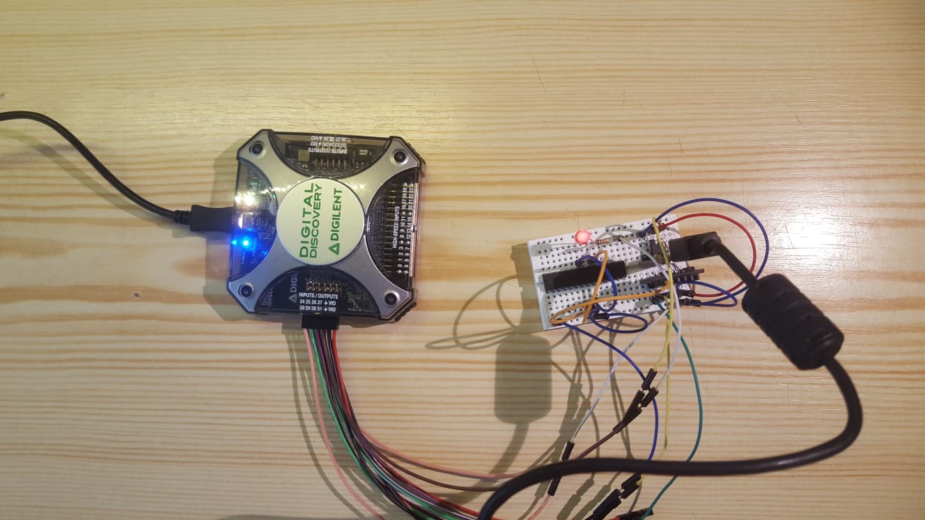
In this example, the MCU will switch an LED on and off, according to the state of a control pin. The LED is connected between the PB5 pin (Arduino pin 13) and the ground. The control pin is PB1 (Arduino pin 9), so this should be pulled down with a 10KΩ resistor. The MCU is supplied from the A1 pin of the Pmod DA1 digital to analog converter, which is connected to the Digital Discovery. The PB1 pin of the MCU is also connected to the Digital Discovery.
Power to the Pmod DA1 is supplied by the Pmod USBUART, which also comes connected to the Digital Discovery, as well as to the PC through a USB cable.
Software Setup
A LabVIEW Virtual Instrument consists of two parts: the Front Panel and the Block Diagram. The Front Panel contains all controls and indicators for data in- and output and serves as a user interface when the program is running. The Block Diagram contains the blocks which are present on the Front Panel, in addition to other blocks necessary for information processing, and the connections between these blocks. One can add a new block to both windows by right clicking on a blank space in the corresponding window and selecting the required block from a library. Blocks already present in the window can be modified by right clicking on the respective block. The Front Panel and the Block Diagram of this example will be presented.
Double click on the main VI (variable_logic_voltage.vi) of the downloaded example to open it with LabVIEW Community. All the functions and subVIs used in the example can be used in your own VI, play around and see what else you can create.
Note: For this VI to work, the dwf VI library is necessary (see: Creating VIs for a Shared Library).
Front Panel
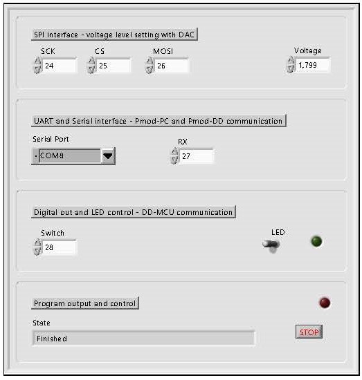
The Front Panel contains, in the upper section, three input fields for defining the DIO lines used as SPI transmitter and a field for voltage control, which can be set to any value between 1.8V and 3.3V.
Below this, there is a drop-down list for selecting the serial port the Pmod USBUART is connected to and an input field to define the DIO line used for receiving UART signals.
In the third box the DIO line connected to the microcontroller can be set. It also contains a switch which will set the state of this pin, and a virtual LED to indicate this state.
In the last box, there is a text field where messages about the current operation are displayed. The Stop button can also be found here, which stops the program and disconnects the Digital Discovery, to make it available for other software. A virtual LED can be found near the Stop button, which indicates if the program is running or not.
Block Diagram
The main VI (variable_logic_voltage.vi) contains several parts separated by decorative and functional structures, as well as multiple subVIs. In the following, these will be presented.
The first block contains functions for first closing every opened Test and Measurement device, then opening the first available device. The state of the virtual LEDs and the textbox containing messages about the state of the program are also initialized. Following that, the digital voltage is configured to be 3.3V, then power on the VIO pins is turned on, using the Voltage_set.vi subVI.
The SPI interface is initialized using a subVI, then the voltage level set by the user is output by the Pmod DA1. The value displayed is also updated, then a 1s delay follows to give time for the microcontroller to start.
In the following, the UART and Serial communication protocols are initialized with the parameters set on the Front Panel.
A while loop is started, in which the state of the switch is checked and compared to its previous value. If the two are not equal, the state of the switch is outputted on the selected Serial port.
After 100ms wait time, the Digital Discovery DIO pin connected to the MCU, is pulled LOW, the digital voltage is set to be 3.3V, then the Digital Discovery reads the incoming command on UART (data coming from the Pmod USBUART).
The digital voltage is set to the level indicated on the Front Panel, then the DIO pin connected to the MCU is pulled up/down, according to the data read on UART. This way, the command received with a 3.3V voltage level from the Pmod USBUART is sent to the MCU using a lower, selectable, digital voltage.
The program waits for a change in the state of the switch, or, if the Stop button was pressed or there was an error, exits the loop.
After the loop is exited, all the used instruments are closed, the state of the indicators changed, and possible errors are handled.
Voltage_set.vi
This subVI uses the WaveForms SDK functions from the dwf VI library to set the digital voltage to a certain level between 1.8V and 3.3V, to set the output current to 16mA, and to start/stop the voltage supply pins.
SPI_init.vi
This subVI uses the WaveForms SDK functions from the dwf VI library to initialize SPI transmission from a connected Test and Measurement device. After the clock frequency is set, the clock and the MOSI line are specified. In default mode, the pins of the Digital Discovery are numbered from DIO 24, so 24 has to be subtracted from the inputted numbers.
The idle state of the data line is set (default is high impedance state), then the SPI mode (0) and the endianness (MSB first) are set. The chip select line is specified and pulled up. Finally a dummy write command is issued while keeping the chip select high, to initialize the serial clock.
DAC_set.vi
This subVI uses the WaveForms SDK functions from the dwf VI library to pull the chip select line low, send a 16-bit data word on SPI interface, then pull the chip select line up. The first 8 bits of the data word are the command to set only the A1 channel of the DAC (0x10). The last 8 bits correspond to the desired voltage level (3.3V → 0xFF, 0V → 0x00).
UART_init.vi
This subVI uses the WaveForms SDK functions from the dwf VI library to initialize UART reception with a connected Test and Measurement device. After the baud rate is set, RX line is specified. In default mode, the pins of the Digital Discovery are numbered from DIO 24, so 24 has to be subtracted from the inputted numbers.
The idle state of the RX line is set (default is high impedance state), then the number of bits in a word, and the number of stop bits and parity is set. Finally, a dummy read command is issued to initialize the communication.
ON_OFF_ctrl.vi
This subVI uses the WaveForms SDK functions from the dwf VI library to mask the required DIO line (make it available to digital input output), and set a certain logical state on that line.
Testing
After the connections are made and the required communication parameters are set, the program can be started with the Run button on the Front Panel. The virtual LEDs and the text box indicate the current operation. The program can be stopped any time with the Stop button.
References
Final Notes
For more guides and example projects for your Digital Discovery, please visit its Digital Discovery.
For more information about how to use the software featured in this demo, please visit its respective guide: Getting Started with LabVIEW and a Digilent Discovery Device.
For technical support, please visit the Digilent Forums.

