Discovery BNC Adapter Reference Manual
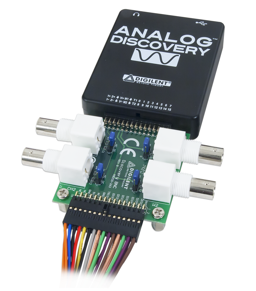
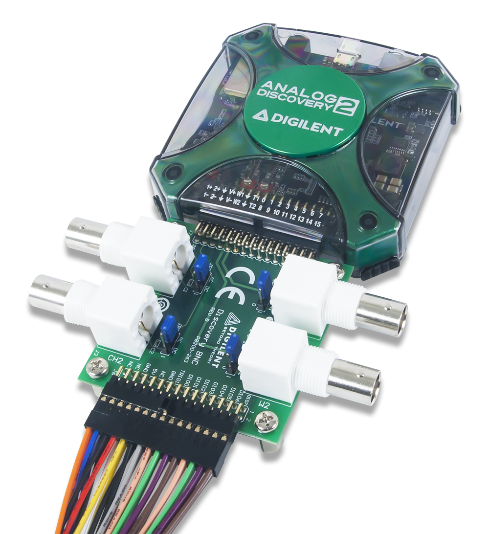
The Discovery BNC adapter board is intended to be used with Digilent's Analog Discovery tool to enable the use of standard BNC terminated test leads and probes. The adapter board enables the user to AC couple or DC couple single-ended signals to the oscilloscope in the Analog Discovery 3 or Analog Discovery 2.
Features
- Standard BNC interface to single-ended BNC terminated test leads and oscilloscope probes.
- Selectable AC and DC coupling to oscilloscope probes.
- Selectable 50-ohm or 0-ohm output impedance on Arbitrary Waveform Generator (AWG) channels.
- Increased oscilloscope bandwidth of up to 50 MHz when used with Digilent BNC probe
Physical Dimensions
The PCB of the BNC Adapter is 6.0 cm (2.36 inches) per side.
Functional Description
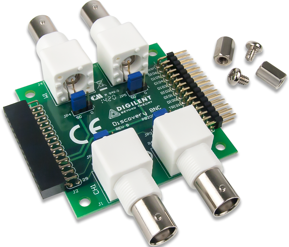
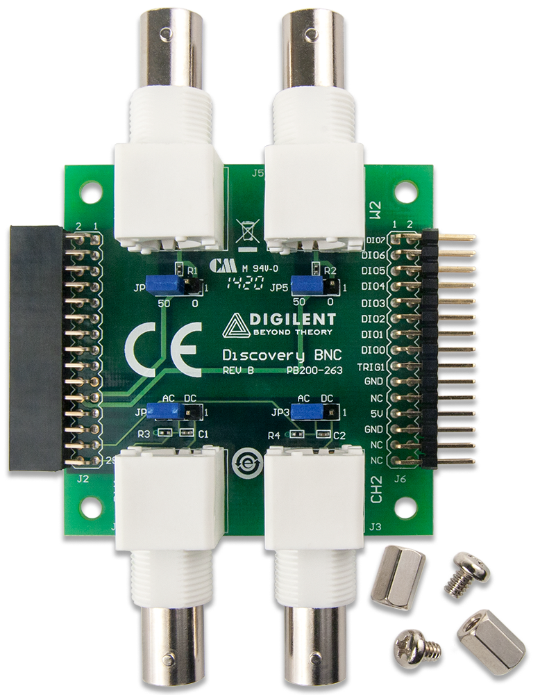
The Discovery BNC adapter board has BNC terminations to each of the two oscilloscope channels on the Analog Discovery. Each channel of the oscilloscope can be selected as AC or DC coupled by adjusting the jumper that is located behind that channel's BNC input connector. Note that the negative inputs for both oscilloscope channels are tied to ground, creating single ended inputs with the BNC Adapter board.
The two AWG channels are equipped with BNC terminations for use with BNC style test leads. Each of the two channels can have either the 50Ω or the 0Ω termination selected. This enables the user to match the Analog Discovery's output impedance with either standard 50-ohm test leads or to be directly tied to the lead.
All the remaining signals from the Analog Discovery pass through the adapter to a female header located on the outer edge of the board.
Pinout Diagram
| Header J2 | Header J6 | J1 (scope 1) | JP2 (scope 1) | ||||||||
|---|---|---|---|---|---|---|---|---|---|---|---|
| Pin 1 | DIO 7 | Pin 2 | DIO 15 | Pin 1 | DIO 7 | Pin 2 | DIO 15 | Pin 1 | VIN_SC1_P | DC coupled | Direct connection from the BNC probe to the Scope input |
| Pin 3 | DIO 6 | Pin 4 | DIO 14 | Pin 3 | DIO 6 | Pin 4 | DIO 14 | Pin 2 | Ground | AC coupled | Connection from the BNC probe through the high pass filter to the Scope input |
| Pin 5 | DIO 5 | Pin 6 | DIO 13 | Pin 5 | DIO 5 | Pin 6 | DIO 13 | J3 (scope 2) | JP3 (scope 2) | ||
| Pin 7 | DIO 4 | Pin 8 | DIO 12 | Pin 7 | DIO 4 | Pin 8 | DIO 12 | Pin 1 | VIN_SC2_P | DC coupled | Direct connection from the BNC probe to the Scope input |
| Pin 9 | DIO 3 | Pin 10 | DIO 11 | Pin 9 | DIO 3 | Pin 10 | DIO 11 | Pin 2 | Ground | AC coupled | Connection from the BNC probe through the high pass filter to the Scope input |
| Pin 11 | DIO 2 | Pin 12 | DIO 10 | Pin 11 | DIO 2 | Pin 12 | DIO 10 | J5 (AWG 2) | JP5 (AWG 2) | ||
| Pin 13 | DIO 1 | Pin 14 | DIO 9 | Pin 13 | DIO 1 | Pin 14 | DIO 9 | Pin 1 | VOUT_AWG2 | 0 Ohm | 0 Ohm Termination for the AWG |
| Pin 15 | DIO 0 | Pin 16 | DIO 8 | Pin 15 | DIO 0 | Pin 16 | DIO 8 | Pin 2 | Ground | 50 Ohm | 50 Ohm Termination for the AWG |
| Pin 17 | TRIG_1 | Pin 18 | TRIG_2 | Pin 17 | TRIG_1 | Pin 18 | TRIG_2 | J4 (AWG 1) | JP4 (AWG1) | ||
| Pin 19 | WGND | Pin 20 | GND | Pin 19 | GND | Pin 20 | GND | Pin 1 | VOUT_AWG1 | 0 Ohm | 0 Ohm Termination for the AWG |
| Pin 21 | VOUT_AWG1 | Pin 22 | VOUT_AWG2 | Pin 21 | NC | Pin 22 | NC | Pin 2 | Ground | 50 Ohm | 50 Ohm Termination for the AWG |
| Pin 23 | VOUT5V0_USR | Pin 24 | VOUT-5V0_USR | Pin 23 | VOUT5V0_USR | Pin 24 | VOUT-5V0_USR | ||||
| Pin 25 | SGND | Pin 26 | GND | Pin 25 | GND | Pin 26 | GND | ||||
| Pin 27 | VIN_SC2_P | Pin 28 | SGND | Pin 27 | NC | Pin 28 | NC | ||||
| Pin 29 | VIN_SC1_P | Pin 30 | SGND | Pin 29 | NC | Pin 30 | NC | ||||