Analog Discovery Pro (ADP5250) Reference Manual


Oscilloscope
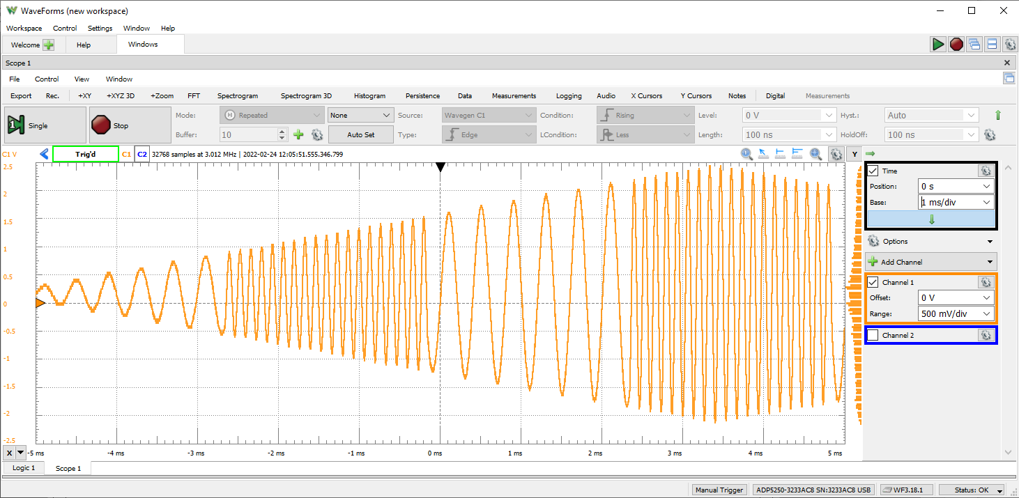
The Analog Discovery Pro (ADP5250) can be used with WaveForms’ Oscilloscope instrument to capture analog data via the 2 analog input channels using BNC probes.
Since the Analog Discovery Pro’s analog input channels are shared, the Oscilloscope instrument cannot be used at the same time as the Spectrum Analyzer, Network Analyzer, or Impedance Analyzer instruments.
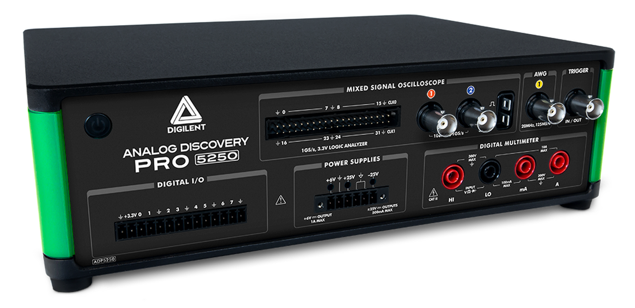
The Analog Discovery Pro features an additional connector, found just to the right of the analog input channels, that provides a square wave for use in compensating your probes. By connecting the probe to the tab indicated by the square wave symbol and the ground clip to the tab indicated by the ground symbol, a 5 V, 1 kHz, square wave reference signal can be measured using the Scope instrument. If your probes support adjusting the compensation, you can then do so, by minimizing the over/undershoot of the measured reference signal.
For more information on the analog input (“Scope”) channels, please visit the Analog Discovery Pro (ADP5250) Specifications. For a walkthrough of the different features of WaveForms' Oscilloscope instrument, please visit the Using the Oscilloscope guide.
Features
- Triggering: edge with hysteresis
- Cross-triggering with Logic Analyzer, Waveform Generator, or external trigger
- Sampling modes: average, decimate, min/max
- Mixed signal visualization (analog and digital signals share same view pane)
- Real-time views: FFTs, XY plots, histograms, spectrograms, and others
- Multiple math channels with complex functions
- Cursors with advanced data measurements
- Captured data files can be exported in standard formats
- Scope configurations can be saved, exported, and imported
- Front panel connector generating a 5 V, 1 kHz, square wave for convenient compensation of BNC oscilloscope probes
Waveform Generator

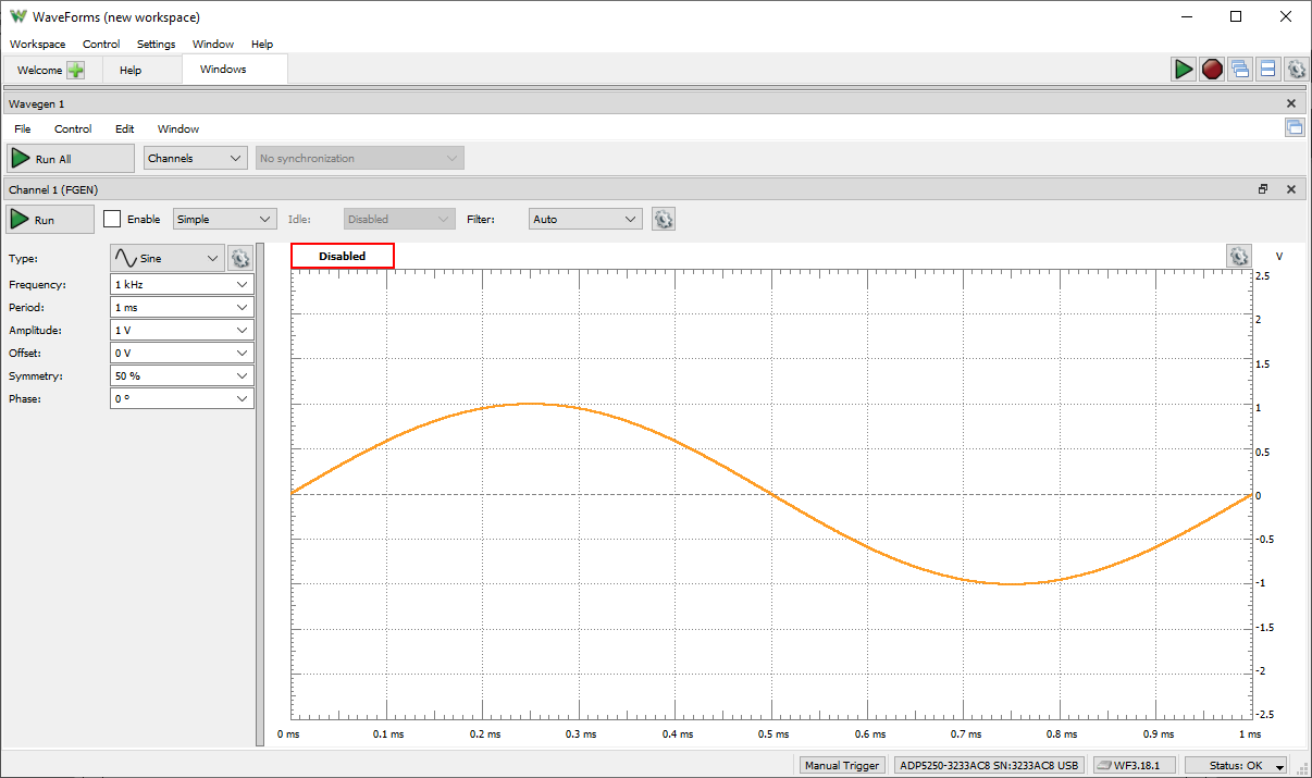
The Analog Discovery Pro (ADP5250) can be used with WaveForms' Wavegen instrument to output analog voltage waves via BNC cable. The Waveform Generator converts digital samples to analog and stimulates a circuit connected over a single channel. When the Wavegen instrument is used, the Analog Discovery Pro's analog output channel acts as an Arbitrary Waveform Generator. The instrument supports everything from simple waveforms like Sine and Triangle waves or custom sets of samples can be defined by the user in applications like Excel and imported to WaveForms.
The waveform generator channel is considered a single ended pin, however, a connected circuit must share a ground with the Analog Discovery Pro.
Since the Analog Discovery Pro's analog output channel is shared, the Waveform Generator instrument cannot be used at the same time as the Network Analyzer, or Impedance Analyzer instruments.
For more information on the analog output (“Wavegen”) channel, please visit the Analog Discovery Pro (ADP5250) Specifications. For a walkthrough of the different features of WaveForms' Waveform Generator instrument, please visit the Using the Waveform Generator guide.
Features
- Standard waveforms: sine, triangle, sawtooth, noise, and many others
- User-defined arbitrary waveforms: defined within WaveForms software user interface or using standard tools (e.g. Excel)
Power Supplies

The Analog Discovery Pro (ADP5250) has 3 programmable Digital Voltage Supplies, which can supply between 0 V to +6 V, 0 V to +25 V, and 0 V to -25 V through the Power Supplies (“Supplies”) instrument.
Each of the power supply rails is associated with an LED available on the connector, just above the supply's screw terminal, which is used to indicate the operating mode of that supply. When a load doesn't require more current than the supply's current limit, the supply operates in Constant Voltage (CV) mode, and the indicator LED is blue. When the load does try to draw more current than the current limit, the supply operates in Constant Current (CC) mode, and the LED is orange. WaveForms' Supplies instrument UI for the ADP5250 also features these LEDs, showing CV mode with a green indicator and CC with a red indicator.
For more information on using the programmable power supplies, please visit the Analog Discovery Pro (ADP5250) Specifications. For a walkthrough of the different features of WaveForms' Power Supplies instrument, please visit the Using Power Supplies with a Readback Plot guide.
Features
- Three programmable power supplies
- 0 V to 6 V (0 A to 1 A)
- 0 V to +25 V (0 mA to 500 mA)
- 0 V to -25 V (0 mA to 500 mA)
- Up to 1A output current
Data Logger

The Analog Discovery Pro (ADP5250) can be used with WaveForms' “Logger” instrument in order to capture large buffers of analog input data on both Scope channels.
The Data Logger can capture buffers of data at update rates of up to 10 samples per second. The maximum duration of a log is dependent on the update rate, but at the extreme, can run for over a thousand hours.
Since the Analog Discovery Pro's analog input channels are shared, the Data Logger instrument cannot be used at the same time as the Oscilloscope, Spectrum Analyzer, Network Analyzer, or Impedance Analyzer instruments.
For more information on the analog input (“Scope”) channels, please visit the Analog Discovery Pro (ADP5250) Specifications. For a walkthrough of the different features of WaveForms' Data Logger instrument, please visit the Using the Data Logger guide.
Features
- Measurements: DC, AC RMS, True RMS, with Averages, Minimums, and Maximums
- Up to 24 hours of data logged at a 1 Hz sample rate
- Scriptable conversion functions
Logic Analyzer

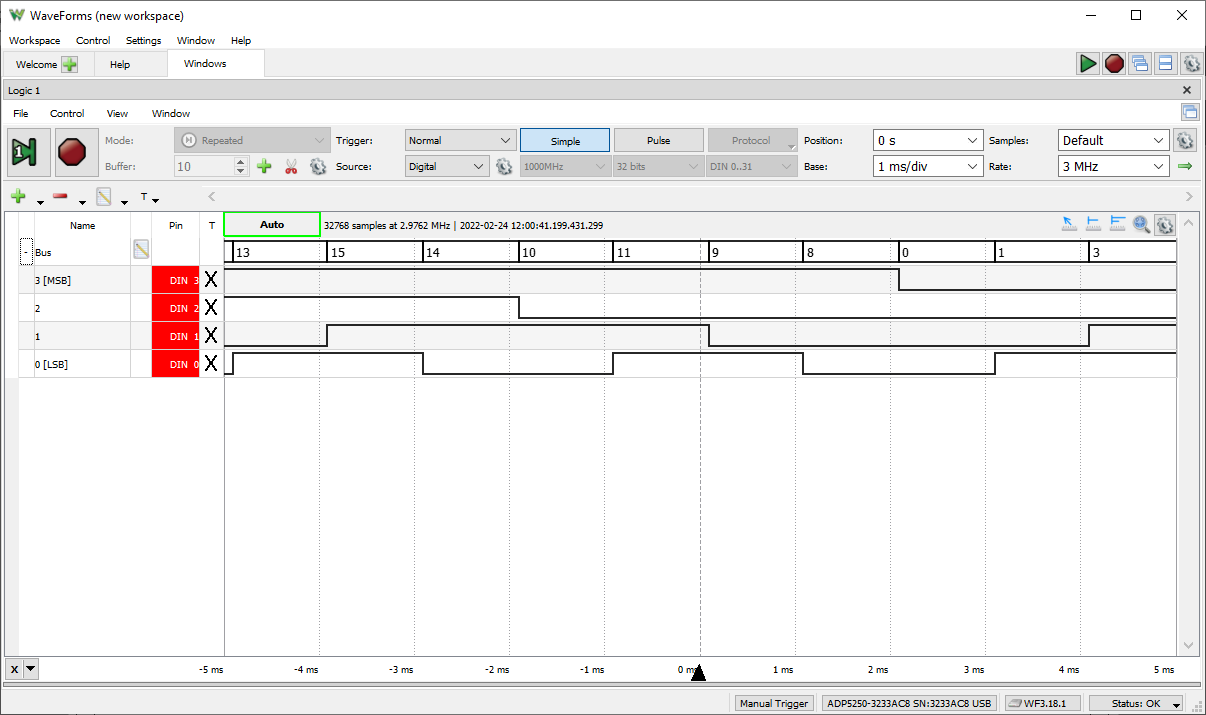
The Analog Discovery Pro (ADP5250) can be used with WaveForms' “Logic” instrument to act as a Logic Analyzer. When used this way, the digital input channels (in the “Logic Analyzer” connector, part of the Mixed Signal Oscilloscope) are configured to capture the high/low logic states over time of connected digital signals.
Individual input/output channels can be grouped as buses and protocols. Protocol groups can be used to view the decoded contents of packets of many common communications protocols, including SPI, I2C, UART, CAN, and I2S.
Signal states, decoded bus values, and decoded protocols can be used to trigger a Logic Analyzer capture. Protocol triggers include protocol-specific events, like start of transmission, end of transmission, or packet contents matching a value.
Digital input/output channels used by the Logic Analyzer instrument can still be used by other instruments using the same digital input/output channels.
For more information on the digital input/output channels, please visit the Analog Discovery Pro (ADP5250) Specifications. For a walkthrough of the different features of WaveForms' Logic Analyzer instrument, please visit the Using the Logic Analyzer guide.
Features
- Multiple trigger options including pin change, bus pattern, and many others
- Cross-triggering between Analog input channels, Logic Analyzer, Pattern Generator, or external trigger
- Interpreter for SPI, I2C, UART, CAN, I2S, 1-Wire, parallel buses
- Scripted custom protocols
- Data file import/export using standard formats
Static I/O
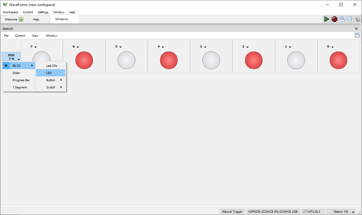
The Analog Discovery Pro (ADP5250) can be used with WaveForms' Static I/O instrument to emulate a variety of user input/output devices on the digital input/output pins. Virtual LEDs, buttons, switches, sliders, and displays can be assigned to specific digital I/O pins, found on the “Digital I/O” connector, and interacted with within the WaveForms user interface.
Important Note: To prevent damage to the device, care must be taken not to drive input signals to the digital input/output channels over 5 V.
Digital input/output channels used by the Static I/O instrument can still be used by other instruments using the same digital input/output channels, however, other instruments can only use these shared channels as inputs.
For more information on the digital input/output channels, please visit the Analog Discovery Pro (ADP5250) Specifications. For a walkthrough of the different features of WaveForms' Static I/O instrument, please visit the Using the Static I/O guide.
Features
- Virtual I/O devices (LEDs, buttons, switches & displays)
- Customized visualization options available
Spectrum Analyzer
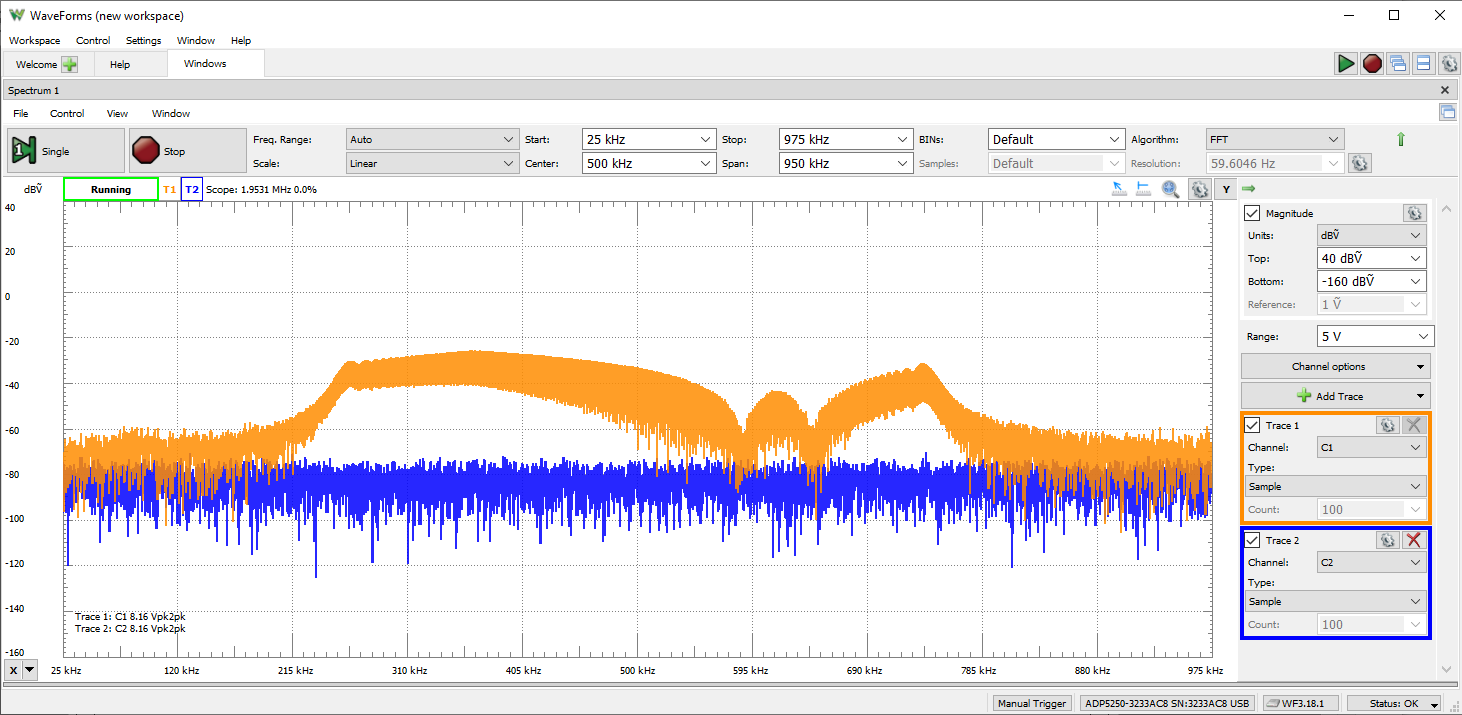
The Analog Discovery Pro (ADP5250) can be used with WaveForms' “Spectrum” instrument to view the power of frequency-domain components of analog signals captured on the analog input channels.
Signals can be plotted in units of peak voltage, RMS voltage, and various voltage level ratio units.
Since the Spectrum Analyzer instrument uses the same hardware resources as the Oscilloscope, Network Analyzer, and Impedance Analyzer instruments, it cannot be used at the same time as these other instruments.
For more information on the analog input channels, please visit the Analog Discovery Pro (ADP5250) Specifications. For a walkthrough of the different features of WaveForms' Spectrum Analyzer instrument, please visit the Using the Spectrum Analyzer guide.
Features
- Power spectrum algorithms: FFT, CZT
- Frequency range modes: center/span, start/stop
- Frequency scales: linear, logarithmic
- Vertical axis options: voltage-peak, voltage-RMS, dBV, and dBu
- Windowing: options: rectangular, triangular, hamming, cosine, and many others
- Cursors and automatic measurements: noise floor, SFDR, SNR, THD and many others
- Data file import/export using standard formats
Network Analyzer

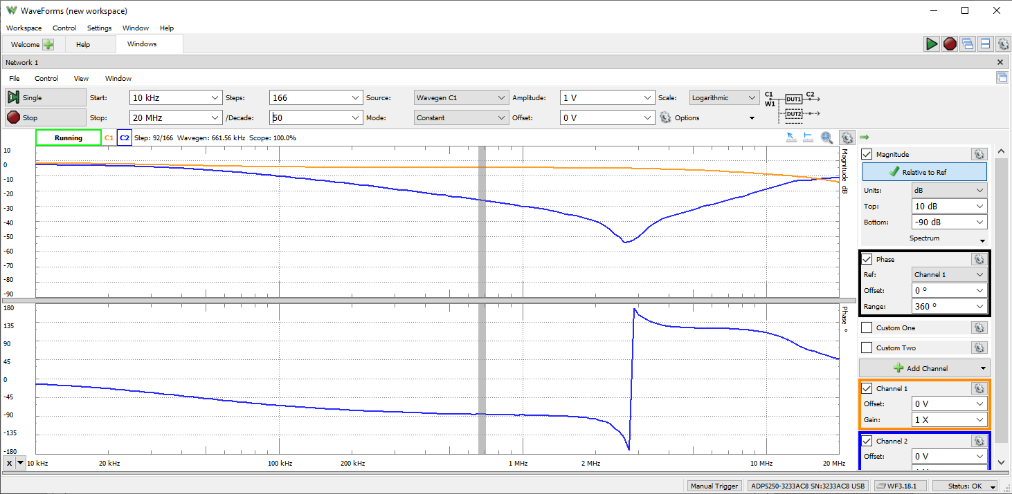
The Analog Discovery Pro (ADP5250) can be used with WaveForms' “Network” instrument to view the amplitude and phase response of a circuit under test. Nichols and Nyquist plots can also be viewed with this instrument.
Frequency sweeps can be performed in ranges between 1 mHz and 10 MHz with up to 10k samples per decade. The wave used for the sweep can be customized, and uses the same resources as the Waveform Generator instrument.
The Network Analyzer instrument uses the analog output and analog input channels of the Analog Discovery Pro (ADP5250) to probe a test circuit. The Network Analyzer can be configured to use an external signal to provide input to the circuit under test, rather than using the analog output channels.
Since the Analog Discovery Pro's analog input and output channels are shared, the Network Analyzer instrument cannot be used at the same time as the Oscilloscope, Waveform Generator, Data Logger, Spectrum Analyzer, or Impedance Analyzer instruments.
For more information on the analog output and analog input channels, please visit the Analog Discovery Pro (ADP5250) Specifications. For a walkthrough of the different features of WaveForms' Network Analyzer instrument, please visit the Using the Network Analyzer guide.
Features
- Available diagrams: Bode, Nichols, Nyquist, and FFTs
- Settable input amplitude and offset
- Analog input records response at each frequency
Impedance Analyzer
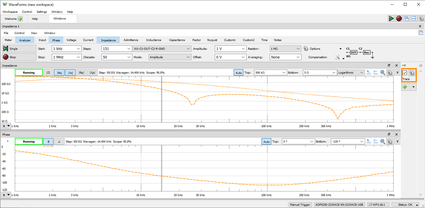
The Analog Discovery Pro (ADP5250) can be used with WaveForms' “Impedance” instrument to view a wide variety of frequency response characteristics of a circuit under test. Input, Phase, Voltage, Current, Impedance, Admittance, Inductance, Factor, and Nyquist plots are all available. In addition, Custom plots can be used to present the results of a wide variety of different mathematical operations on buffered data.
Frequency sweeps are performed to stimulate the connected circuit and measure the response. The signal used in the sweeps can be selected from a variety of presets, with configurable amplitude and offset. An external network analyzer reference circuit can be selected from a variety of options.
The Impedance Analyzer instrument uses the Analog Discovery Pro's analog output channels and analog input channels to probe a test circuit.
Since the Analog Discovery Pro's analog input and output channels are shared, the Impedance Analyzer instrument cannot be used at the same time as the Oscilloscope, Waveform Generator, Data Logger, Spectrum Analyzer, or Network Analyzer instruments.
For more information on the analog output and analog input channels, please visit the Analog Discovery Pro (ADP5250) Specifications. For a walkthrough of the different features of WaveForms' Impedance Analyzer instrument, please visit the Using the Impedance Analyzer guide.
Features
- Chart views for Voltage, Current, Impedance, Admittance, Capacitance, and others
- Alternative simple Meter view
- Selectable external compensation circuit
- Data file export using standard formats
WaveForms Script Editor
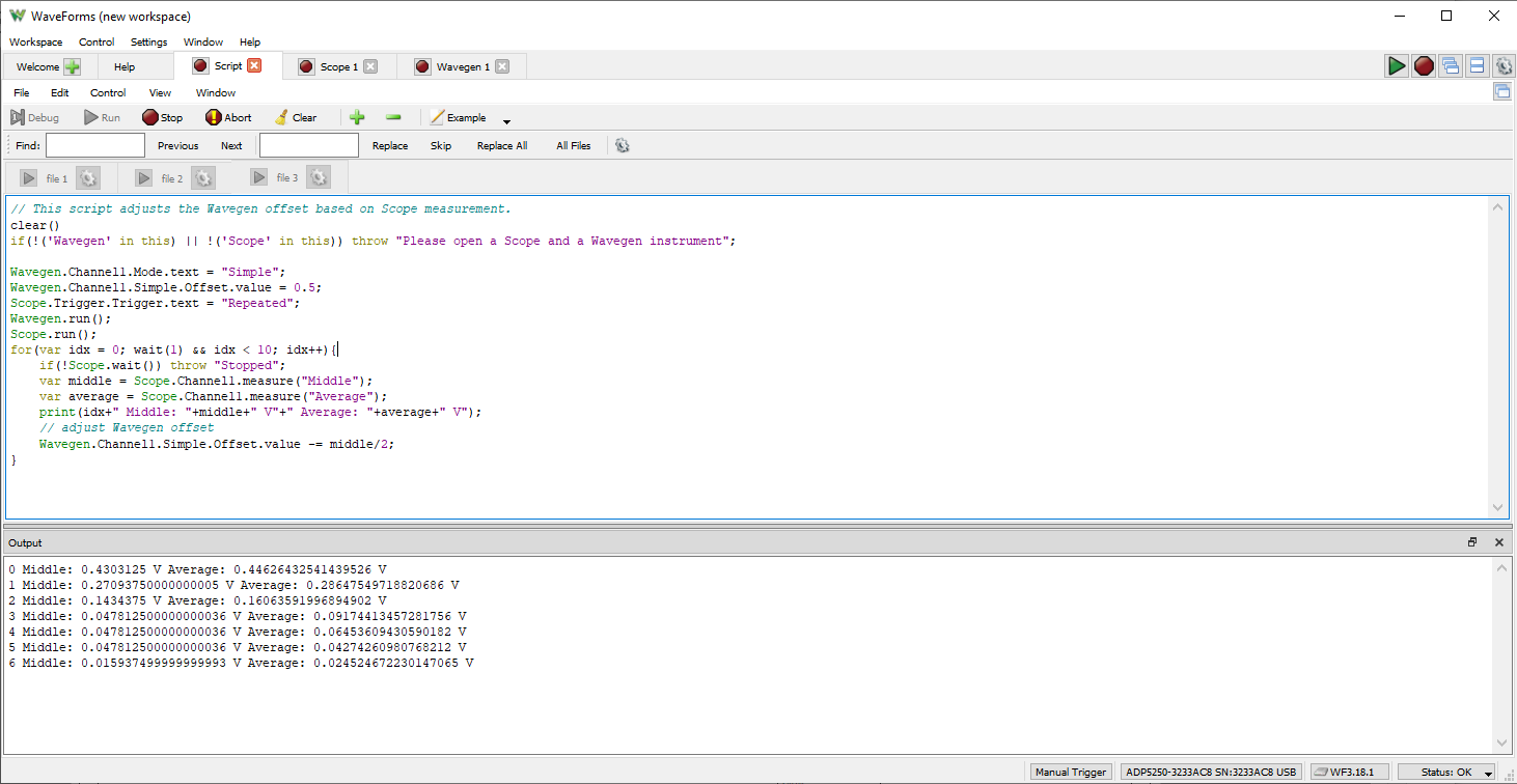
Each of WaveForms' instruments can be controlled through scripts within the WaveForms application itself. WaveForms' “Script” instrument allows the user to write and run JavaScript code that can control the rest of the application through an extensive API. This allows the user to configure and run many instruments at the same time, in an easily repeatable way.
A variety of code examples are available in the application to aid in learning to write WaveForms scripts. Additional resources for writing scripts can be found on the Test and Measurement section of the Digilent Forum.
A plot pane within the Script instrument itself can be used to integrate data from many different instruments, and display it in a highly customizable way.
For a walkthrough of the different features of WaveForms' Script instrument, please visit the Using Scripts guide.
Features
- Available within the WaveForms application
- Simultaneous control of all instruments through JavaScript
- Automatable GUI actions
- Custom data analysis and manipulation functions
WaveForms Software Development Kit (SDK)
WaveForms SDK is a set of software libraries and examples that can be used to develop custom applications that can control Digilent Test and Measurement devices. Supported languages include C, C++, C#, Visual Basic, and Python. More information about WaveForms SDK can be found through the WaveForms SDK Resource Center.
Features
- Downloaded via the WaveForms installer, used independently of the WaveForms application
- Languages supported: C/C++, C#, Python, Visual Basic
- Provides control of hardware channels and virtual instruments to custom applications
Note: For custom applications we recommend and support WaveForms SDK, however, NI’s VirtualBench C API and VirtualBench LabVIEW Vis can also be used.