RC Low-Pass Filter Model vs Real Behavior

Introduction
This project performs a frequency sweep from 1kHz to 100kHz on a low-pass RC circuit. The input and output signals are plotted alongside a mathematically modeled signal based on the desired cutoff frequency and capacitor value. The script generates the resistor value needed to achieve the specified cutoff frequency. This project showcases WaveForms' ability to simulate the effects of circuits on a signal, and to aid in comparing those signals to the real circuit performance.
Inventory
- A Digilent Test and Measurement device that supports WaveForms' Scope and Wavegen instruments.
- An Analog Discovery (Legacy) can also be used.
- WaveForms Installation
-
- Includes a WaveForms workspace including a script that handles the creation of a stimulus waveform, re-capturing it, capturing the circuit's response to it, and modeling the response.
- Components for a low-pass RC circuit:
- Breadboard (recommended)
- Capacitor (any value in the nano-Farad range)
- Potentiometer (any value)
Description
Mathematical models of circuits can be used to predict the performance of the real circuit, but the model should be verified in practice by comparing its results with the results of real circuits.
In order to perform the comparison, a small external circuit will need to be constructed. The modeled response of the filter is calculated using a Math Channel in WaveForms, which implements the formulas used to calculate the output voltage of an low-pass RC filter for a given frequency. Since the frequency sweep is linear, the frequency is known at every point in time, and thus the filter's momentary response can be calculated. The script also models the phase shift introduced by the RC filter.
Setup Instructions
Hardware Setup
This project requires a small external circuit on which to perform the frequency sweep. The circuit consists of a capacitor and resistor in a low-pass RC filter configuration. Please refer to Figure 1 while creating this circuit and connecting it to your Test and Measurement device.

Software Setup
Start by downloading and extracting the WaveForms workspace from the ZIP Archive (also linked in the inventory section, above). Open the extracted workspace (filter.dwf3work) in WaveForms.
Measure the capacitor's capacitance and replace the default value set on the first line of the script (in the Script tab, following the comment block). Be sure to pay attention to the order of magnitude and change the second value in “Math.pow()” accordingly (this is the power to raise 10 by). Decide on the desired cutoff frequency, or leave it as is.

Running the Script
Run the script to generate the resistance that the potentiometer is to be set to for the entered capacitor and cutoff frequency. Set the potentiometer to this value and run the script again.
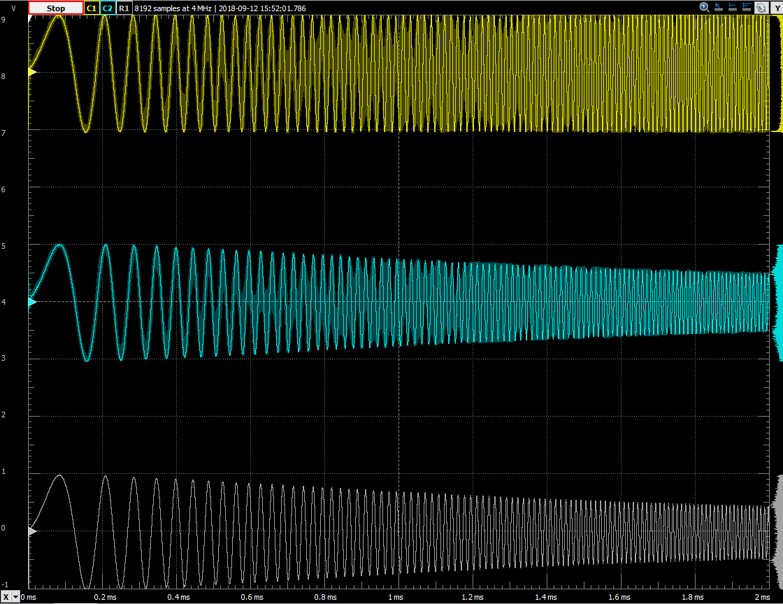
In the Scope 1 tab, Channel 2 (blue) and Ref 1 (gray) should now have extremely similar outputs. Channel 1 (yellow) is the original waveform, “Vin”. Channel 2 (blue) is the real output of the RC filter, “Vout”. Finally, Ref 1 (grey) is the modeled RC filter signal.
The function generator will perform a sweep from 1kHz to 100kHz, but this range can be changed in the Wavegen window.
Final Notes
For more guides and example projects for your Test and Measurement device, please visit its Resource Center, which can be found through this wiki's Test and Measurement page.
For technical support, please visit the Digilent Forums.