Displaying Joystick Position
Introduction
This project streams positional data from the Digilent Pmod JSTK2 into a Digilent Test and Measurement device. The data is presented on an X-Y plot, showing the position of the joystick and any button clicks, similar to a joystick calibration dialog. The project demonstrates how SPI transactions can be generated, and how the results can be plotted and interpreted within WaveForms.
Inventory
- A Digilent Test and Measurement device that supports WaveForms' Scope, Patterns, and Logic instruments.
- An Analog Discovery (Legacy) can also be used.
-
- A Pmod JSTK (Legacy) is pin-compatible and can also be used.
- WaveForms Installation
-
- Includes a WaveForms workspace for displaying positional data captured from the Pmod JSTK2.
Description
The script included in the workspace download is used to initialize several instruments, process captured data, and display it within an X-Y plot.
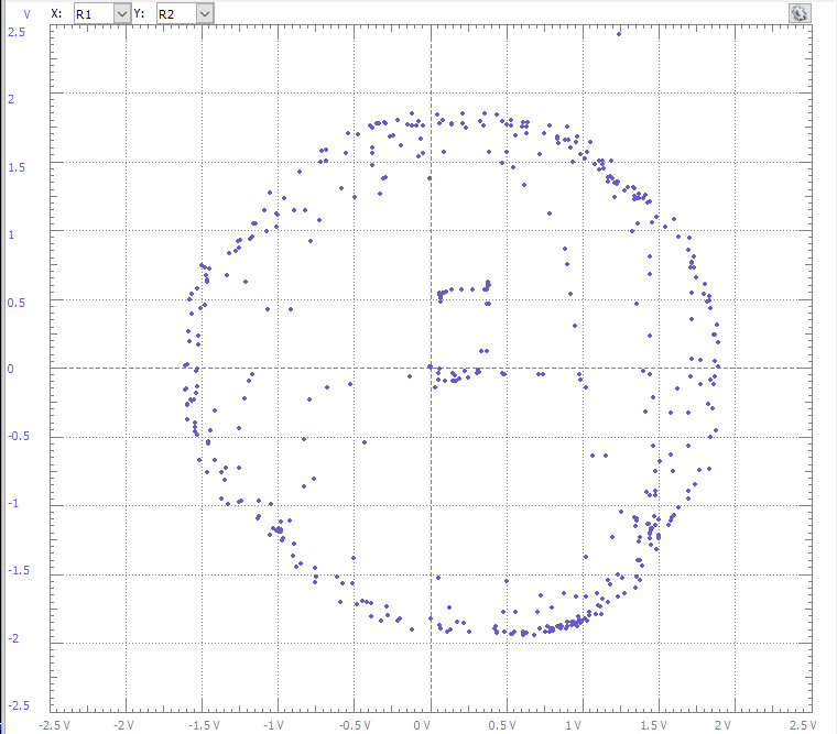
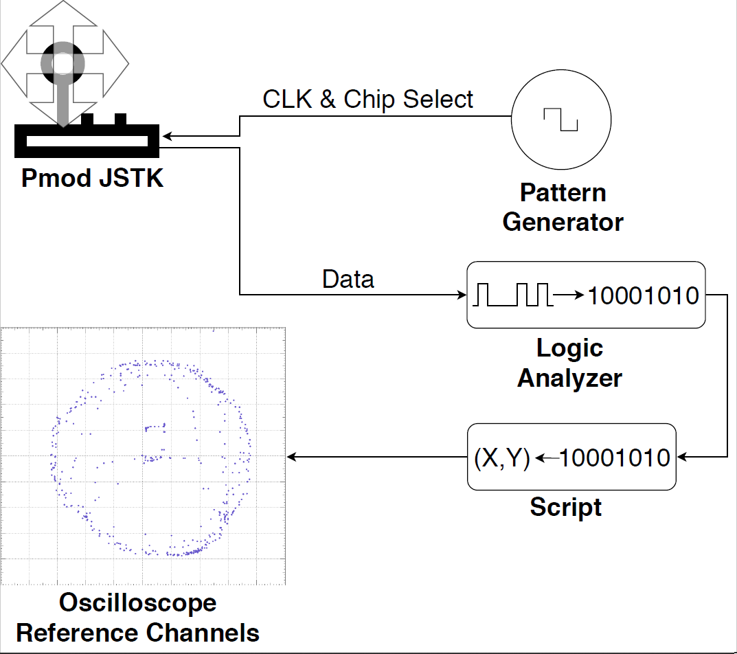
This script utilizes the pattern generator to produce the clock and chip select signals required for SPI communication with the Pmod. The logic analyzer is used to take samples of the data every 5 milliseconds, which is pushed into an array that is displayed in the oscilloscope window as a reference channel. The array contains 500 points, so the X-Y plot will display a trace of the joystick position. When either of the 3 buttons on the Pmod are pressed, the display is cleared and three points in the top portion of the plot represent the left, center, and right buttons.
The script performs bit-wise operations to convert the data into a usable form. As the Pmod JSTK2 Reference Manual states, the X- and Y-coordinates are each passed to the Test and Measurement device as 10 bits contained within 2 bytes. The first byte in the set contains the 8-least significant bits, and the last 2 bits of the second byte are the 2 most-significant bits of the coordinate. The fifth byte indicates the status of the three buttons, represented by the 3 least-significant bits. See the chart below for a visualization of the data. Thus, the data, taken as 16-bit words is processed into a 10-bit number ranging from 0 to 1023. After the number is generated it is added to an array which is displayed as the X-Y plot.
For a better understanding of the what the script is doing, please read the Pmod JSTK2 Reference Manual and see Figure 1, below.
Setup Instructions
1. Hardware Setup
This script requires that Pmod JSTK2 be connected to the test and measurement device's DIO Pins in the following order:
Table 1. Physical Connections
| DIO Pin | Pmod Pin |
|---|---|
| DIO-0 | SS |
| GND | MOSI |
| DIO-1 | CLK |
| DIO-2 | MISO |
| GND | GND |
| V+ | VCC |
2. Software Setup
Start by downloading and extracting the WaveForms workspace from the ZIP Archive (also linked in the inventory section, above).
Once the connections are made, open the extracted workspace (Pmod Joystick.dwf3work) in WaveForms. When selecting the device in the Device Manager dialog, be sure that configuration #4 is selected.
3. Running the Script
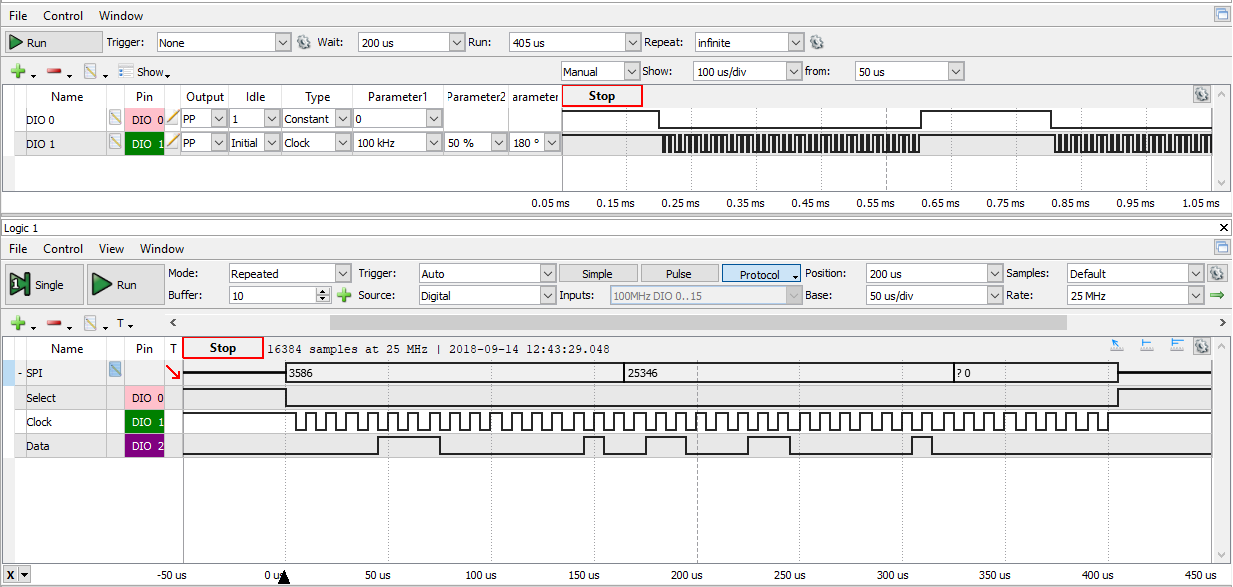
Once the workspace loads, press the Run button in the Script window, or press F5 on the keyboard. The Test and Measurement device will start communicating with the Pmod and streaming the data through the oscilloscope. Moving the joystick will cause the points to move, plotting the position of the control stick. Pressing the left or right buttons or down on the joystick will erase all points on the X-Y plot and display individual points in the top left, right, or middle portion of the plot, respectively. Figures 3 and 4 show the SPI data plotted in the X-Y plot and logic analyzer, respectively.
4. Stopping the Script
When finished, press the Stop button in the Script window, the Stop buttons in the Patterns 1 and Logic 1 windows, and the Master Enable is On button in the Supplies window.
Final Notes
For more guides and example projects for your Test and Measurement device, please visit its Resource Center, which can be found through this wiki's Test and Measurement page.
For more information about how to use the Pmod JSTK2 featured in this demo, please visit its Resource Center.
For technical support, please visit the Digilent Forums.


