Measuring Current with the Analog Discovery 2
The Analog Discovery 2 is an all-in-one pocket instrument for electronics containing a 2-channel oscilloscope, power supplies, waveform generators, logic analyzers, and more to measure and generate analog and digital signals. One thing that the Analog Discovery 2 does not directly do is measure the current flowing through a circuit, but it can be easily calculated and viewed through the WaveForms software.
Inventory
-
- If you haven't already installed WaveForms, you can follow the video installation guides.
- A circuit that needs current measured
Step 1: Set up the Circuit
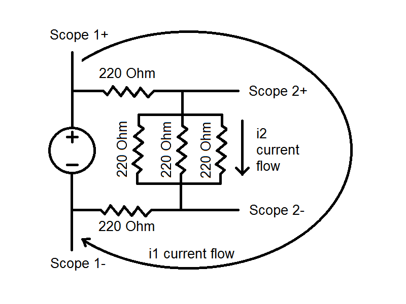
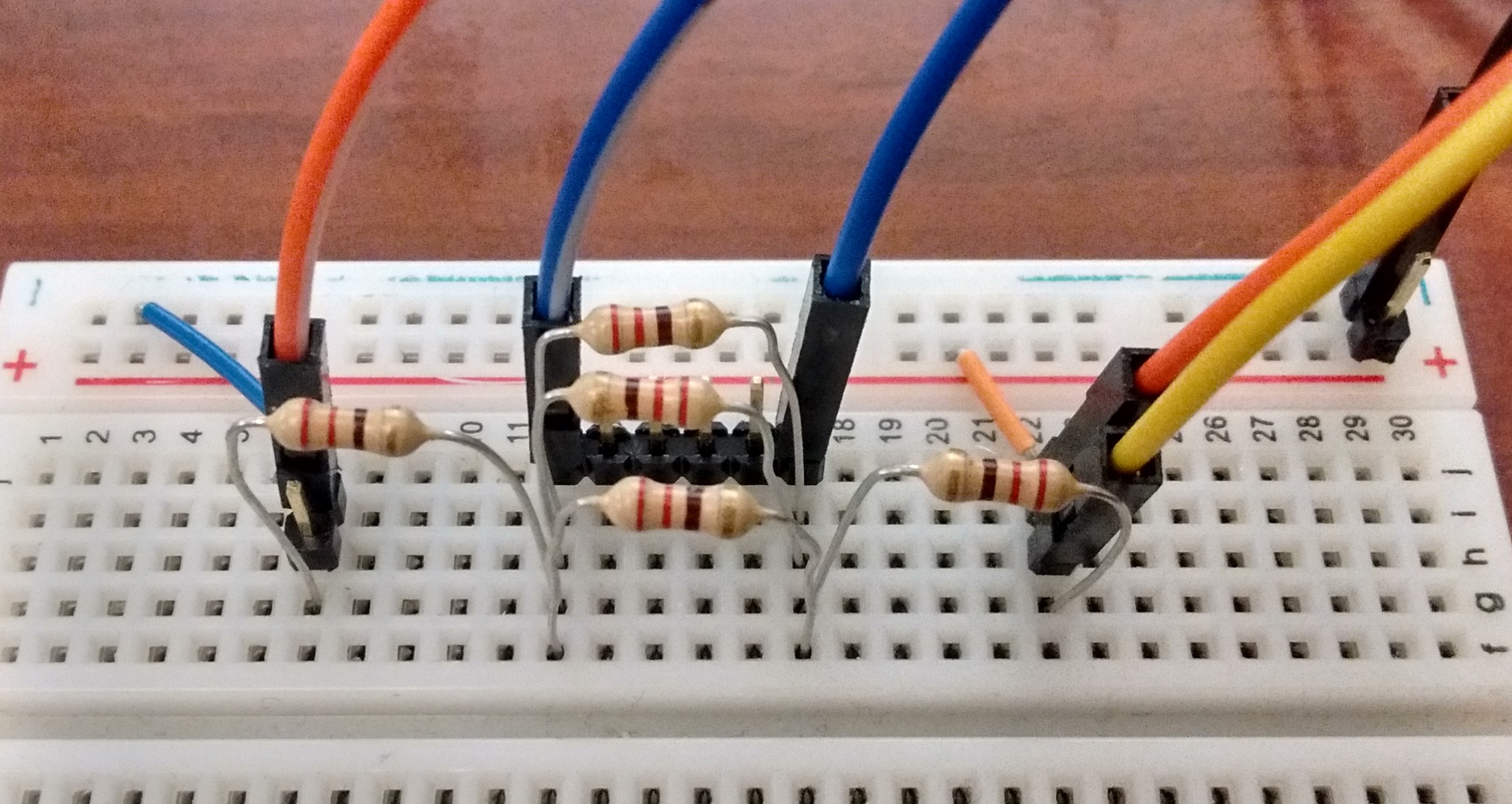
This tutorial will measure the current flowing through both a portion of and the entirety of a resistor network. A schematic of the parallel resistor network and a picture of the setup are provided:
The Analog Discovery 2 cannot measure current directly, but the Math channel can be used to divide the measured voltage over the resistance of the circuit. The resistance of the current for simple circuits made of resistors can be easily measured with a digital multimeter, or more complex circuits can have their resistance measured with the Impedance Analyzer.
Step 2: Set up the Software
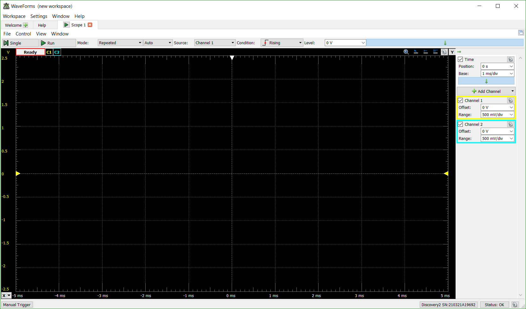
Open up the WaveForms software and connect to your instrumentation module. Click on the ![]() icon to open up the Oscilloscope. Both channel 1 and channel 2 of the oscilloscope should already be enabled on the right-hand side of the screen, so nothing further needs to be done with them.
icon to open up the Oscilloscope. Both channel 1 and channel 2 of the oscilloscope should already be enabled on the right-hand side of the screen, so nothing further needs to be done with them.
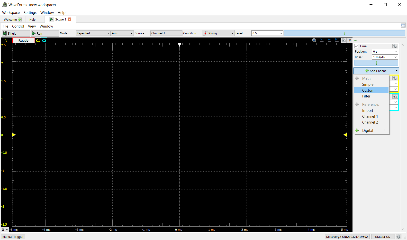
Click on the Add Channel button on the right-hand side of the screen to bring up the option of choosing a custom Math channel.
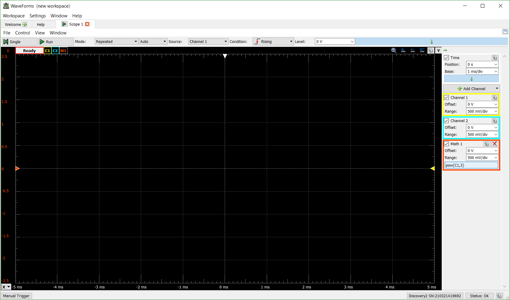
The Math channel will be added to the view, but will have the incorrect equation pre-loaded. Click on the pow(C1,3) portion of the Math channel.
This opens the editing window. A number of premade functions are available to use in variety of combinations as well as the option to use the WaveForms script editor for complex calculations. For a resistor network, Ohms Law can be used to calculate the current, I = V/R. The base unit can also be provided for easy recognition of what is being calculated.
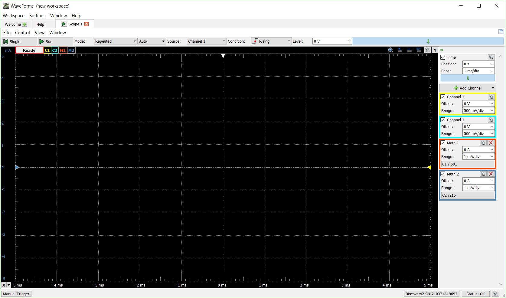
The Oscilloscope channel 1 in this tutorial is measuring the voltage across the entire circuit, so the equivalent resistance for this circuit, using the real values rather than the theoretical values indicated by the resistor color bands is 501.67 Ω. Similarly, the equivalent resistance for the three resistors in parallel measured by Oscilloscope channel 2 is 71.67 Ω. Thus, the Math 1 channel calculates the i1 current by performing C1 / 501.67 and the Math 2 channel calculates the i2 current by dividing C2 by 71.67. For this particular circuit with the chosen resistors and planned voltage input of 1 V to 5 V, the range for each Math channel was set to 5 mA/div.
Go back to the Welcome page in WaveForms and open up either the Power Supplies by clicking on the ![]() icon or the Arbitrary WaveForm Generator by clicking on the
icon or the Arbitrary WaveForm Generator by clicking on the ![]() icon.
icon.
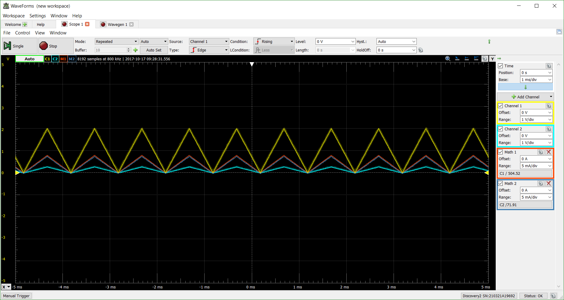
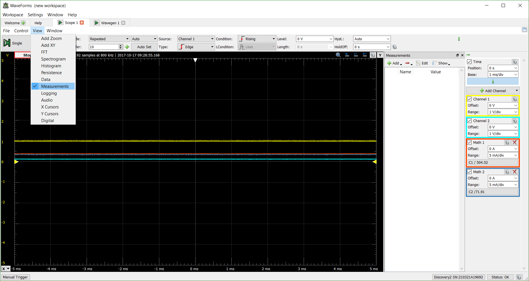
The Power Supplies provides a constant, user-set voltage when the AD2 is powered through USB power. The AWG does not provide as much current, but does provide the option of a set DC voltage signal or a variety of preset or custom waveforms to apply to the resistor network. Below is the resulting oscilloscope view when a DC voltage of 3.3 V is applied as well as the resulting view of a triangle waveform with an offset of 1 V and an amplitude of 1 V.
Specific current values can be viewed by clicking on the X cursor button in the lower-left hand corner of the screen or by adding a Measurements screen from the View menu at the top of the GUI.
Further questions about calculating current with the Analog Discovery 2 and the WaveForms software can be posted on the Digilent Forum where one of the Digilent engineers will be able to see and respond to your question.

