Getting Started with the Breadboard Breakout for Analog Discovery
This guide will walk through the process of setting up a simple circuit, applying a waveform to it, and reading the results using the Analog Discovery and Breadboard Breakout.
Prerequisites
Hardware
- An Analog Discovery 3 or Analog Discovery 2
- Note that the guide below was written for the AD2, however, there is no functional difference when following the same steps with an AD3.
- A Breadboard Breakout for Analog Discovery
- This can be purchased from its Digilent Store Page.
- A breadboard and circuit to test
- The circuit constructed in this guide requires three identical resistors and several jumper wires.
Software
- Digilent Waveforms
- Follow the Getting Started with Analog Discovery to install Waveforms.
Guide
Set up a Circuit
1.
The image to the right is a diagram of the circuit that will be connected to the Analog Discovery 2 through the Breadboard Breakout. Three 10Ω resistors are used to create a Voltage divider circuit, which will have a waveform applied from the W1 pin of the Analog Discovery 2. The circuit will be grounded to the Analog Discovery 2, and will be probed at the two intermediate nodes using the 1+ and 2+ pins. The The 1- and 2- pins should be grounded to get accurate readings on Analog Channels 1 and 2.

2.
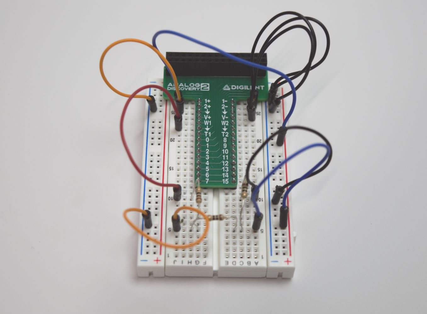
Connect the Breadboard Breakout to the breadboard and construct the circuit. This image shows one way of creating this circuit on a breadboard.

3.
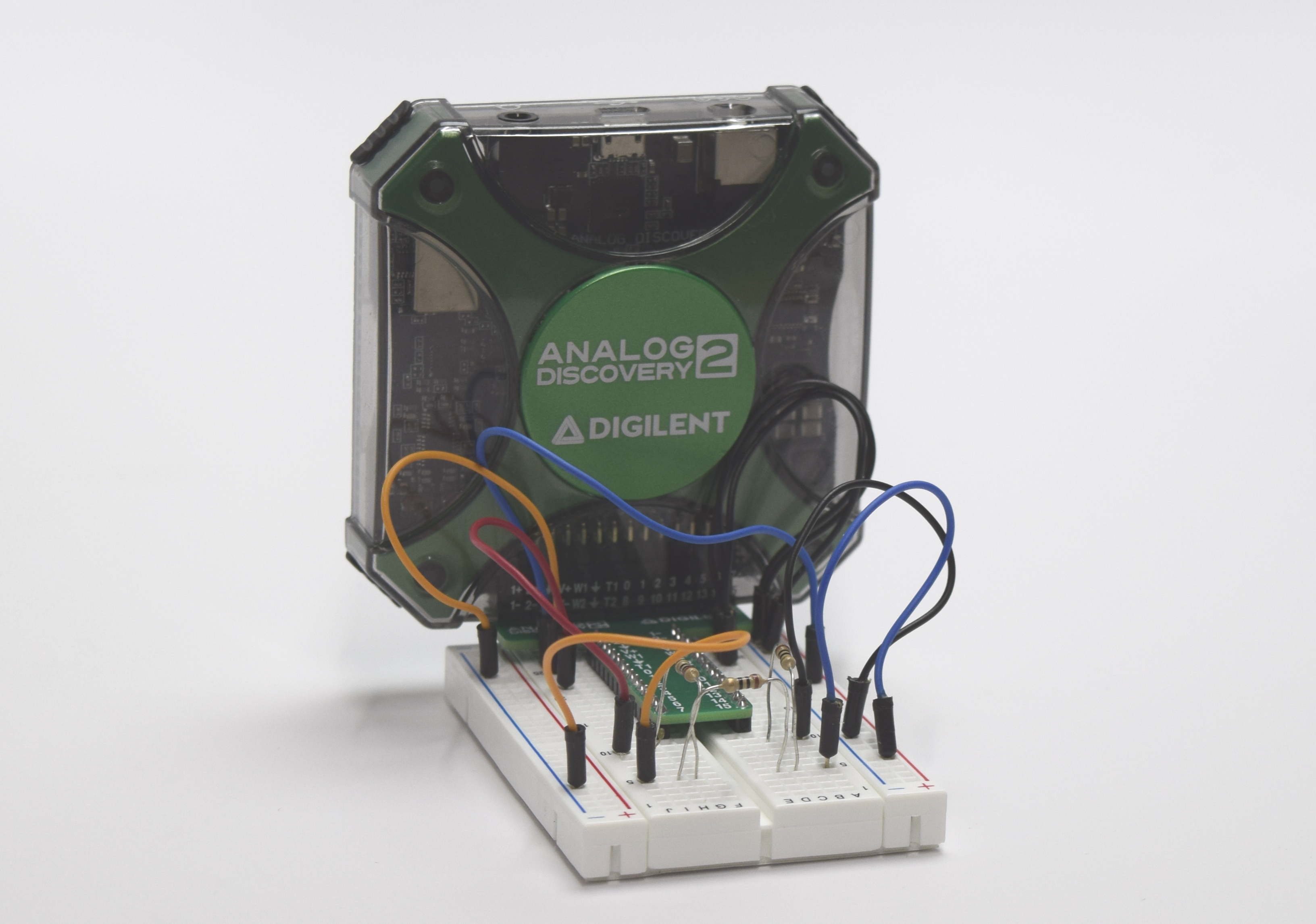
Connect the Analog Discovery 2 to the Breadboard Breakout as in the image to the right.

Use Waveforms to Probe the Circuit
4.
Plug the Analog Discovery 2 into a computer with a microUSB cable and launch Waveforms. Open the Wavegen tab and create a Sine wave at 1kHz frequency and 1V amplitude on Channel 1. Click Run to apply this waveform to the Analog Discovery 2's W1 pin.

5.
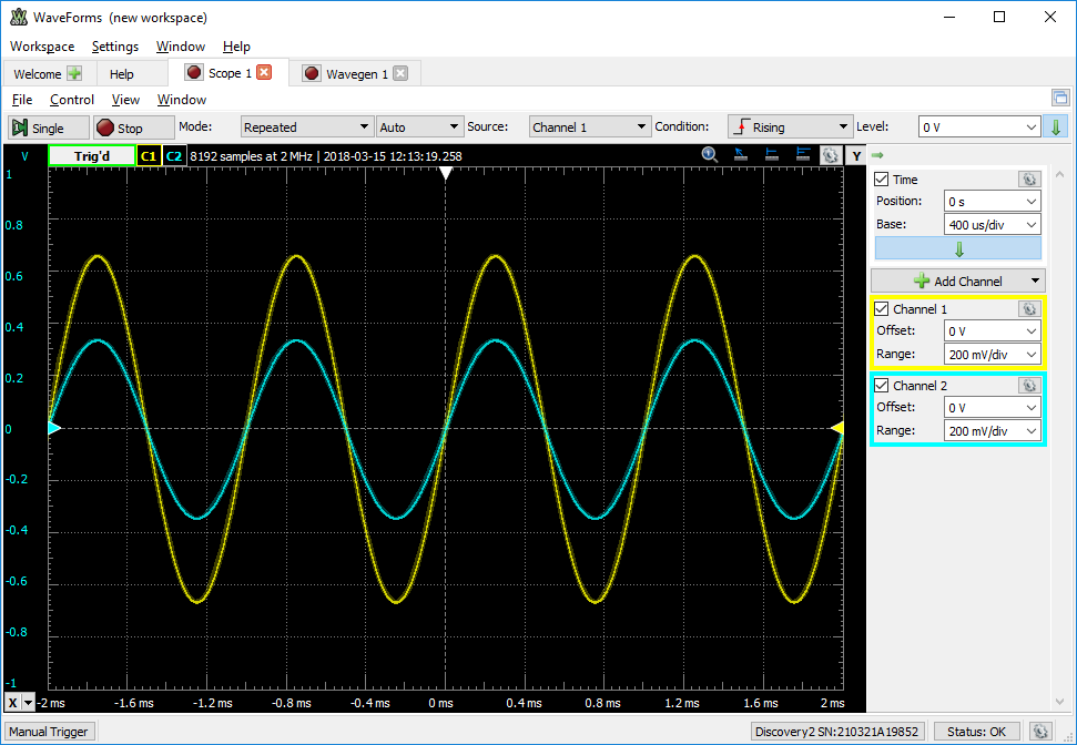
Open the Scope tab. Since both channels of the Analog Discovery 2 scope are already connected to the circuit, enable both channels with an Offset of 0 V and a Range of 200 mV/div. Click Run to begin displaying the waveforms seen at the two intermediate nodes of the voltage divider circuit. As seen in the image to the right, Channel 1 will see a 1kHz Sine wave with an amplitude of 0.67V, while Channel 2 will see a 1kHz Sine wave with an amplitude of 0.33V.

In Conclusion
The Breadboard Breakout for Analog Discovery 2 makes an already-powerful tool that much more easy to use. Play around with it, and see what you can do! Let us know what you think on the Digilent Forum.
