Pmod RS485 Reference Manual
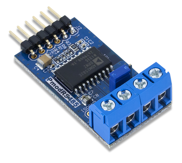
The Digilent Pmod RS485 (Revision B) provides signal and power isolation for high speed communication lines utilizing the RS-485 communication protocol.


Download This Reference Manual
Features
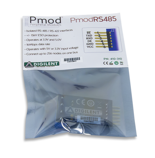
- High-speed RS-485 communication module
- Isolated RS-485/RS-422 interfaces for use in noisy environments
- 16Mbps maximum data rate
- Connect up to 256 nodes on one bus
- Differential half or full-duplex communication
- Thermal shutdown and ±15kV ESD protection
- 6-pin Pmod port with UART interface
Functional Description
The Pmod RS485 utilizes Analog Devices ADM2582E to facilitate RS-485 and RS-422 serial communication protocols between devices in environments with high electrical noise. The ADM2852E provides both signal and power isolation allowing for accurate data transfer across long distances. Data transmission rates of 16 Mbit/s can be achieved.
Interfacing with the Pmod
The Pmod RS485 communicates with the host board via the UART protocol. In order to transmit data, the Driver Enable line must be pulled to a logic level high voltage state; similarly, in order to receive data the Receive Enable line must be driven to a logic level low voltage state.
A truth table indicating the status of the various pins of the Pmod RS485 is provided below:
| Receiving | Transmitting | ||||||
|---|---|---|---|---|---|---|---|
| Inputs | Output | Inputs | Outputs | ||||
| A-B Voltage Difference | ~RE | RxD | DE | TxD | Y | Z | |
| ≥ -0.03V | Low or Not Connected | High | High | High | High | Low | |
| ≤ -0.2V | Low or Not Connected | Low | High | Low | Low | High | |
| -0.2V < A-B < -0.03V | Low or Not Connected | Don't Care | Low | Don't Care | High Impedance | High Impedance | |
| Inputs Open | Low or Not Connected | High | |||||
| Don't Care | High | High Impedance | |||||
")
Pinout Description Table
| Pmod Header J2 | Screw Terminals | ||||
|---|---|---|---|---|---|
| Pin | Signal | Description | Signal | Description | |
| 1 | ~RE | Receive Enable | A | Input A | |
| 2 | TXD | Transmit Data | B | Input B | |
| 3 | RXD | Receive Data | Z | Output Z | |
| 4 | DE | Driver Enable | Y | Output Y | |
| 5 | GND | Power Supply Ground | |||
| 6 | VCC | Positive Power Supply (3.3/5V) | |||
Multiple Pmod RS485 devices can be chained together up to 256 nodes in total. When two Pmod RS485s are connected, JP1 should be loaded on both devices. When more than two Pmod RS485s are connected, JP1 should only be loaded on the two devices at the terminating ends of the wire, and stubs off of the main line should be kept as short as possible.


Any external power applied to the Pmod RS485 must be within 3.0V and 5.5V; however, it is recommended that Pmod is operated at 3.3V.
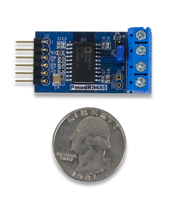
Physical Dimensions
The pins on the pin header are spaced 100 mil apart. The PCB is 1.5 inches long on the sides parallel to the pins on the pin header and 0.8 inches long on the sides perpendicular to the pin header.
Additional Information
The schematics of the Pmod RS485 are available here. Additional information about the RS485 transceiver including communication modes and specific timings of the chip can be found by checking out its datasheet here.
Example code demonstrating how to get information from the Pmod RS485 can be found here.
If you have any questions or comments about the Pmod RS485, feel free to post them under the appropriate section (“Add-on Boards”) of the Digilent Forum.