USB104 A7 Zmod AWG 1411 Demo
Overview
This project demonstrates the implementation of a Zmod AWG 1411 on the USB104 A7.
Description
The simplified block diagram of the system implemented for this demo is shown below:

A console application is used to communicate with the USB104 A7. A typical application would be to send a waveform .csv to the Zmod AWG 1411 and start it. The process of a write operation on channel 1 is as follows:
1. Generate a waveform .csv in Digilent Waveforms. (Instructions below)
2. PC application opens waveform .csv and converts weight values to signed 14 bit values.
3. Write opcode (1) or'ed with channel 1 (1«16) is sent over DPTI.
4. Length of the sample buffer (number of samples * 2 bytes) is sent over DPTI.
5. Sample buffer is sent over DPTI.
6. USB104 A7 receives buffer and writes this buffer to the channel buffer for the Zmod AWG 1411.
After the waveform has been sent, the start command can be sent to start the waveform output from the Zmod AWG 1411 channel 1. The output can be scoped on the Zmod AWG 1411 channel 1.
The IPs instantiated in the design and their functionality are described below:
- ZmodDAC1411 Low Level Controller - initializes the Zmod DAC 1411 hardware and formats the output data according to the AD9717 DAC requirements.
- AXI_ZmodDAC - An AXI interface to communicate with the ZmodDAC Low Level Controller from a software environment. Sends data to the ZmodDAC through DMA.
- AXI_DPTI - Initializes the DPTI interface. Sends and receives data from the DPTI interface through DMA.
- AXI_IIC - An I2C interface to communicate with the ZmodDAC hardware.
- AXI_UARTLITE - A UART interface used to send debugging messages to a COM port on the PC.
Inventory
Hardware
-
- Including a USB A cable and 5V Power Supply
- NOTE: SW1 DDR voltage set to 1.5V
-
- Including a Micro USB cable
Software
- Vivado Design Suite 2019.1 with Digilent Board Support Files installed
- Follow the Installing Vivado, Xilinx SDK, and Digilent Board Files guide on how to install Vivado and Digilent Board Support Files.
-
- Used to read debug messages from the FPGA. Follow the Serial Terminal Emulator Guide for more information on installing and using Tera Term.
Skills
- Basic familiarity with Vivado
- This experience can be found by walking through our “Getting Started with Vivado” guide
- Basic familiarity with Digilent Waveforms
Downloads
Demo Setup
Hardware Setup
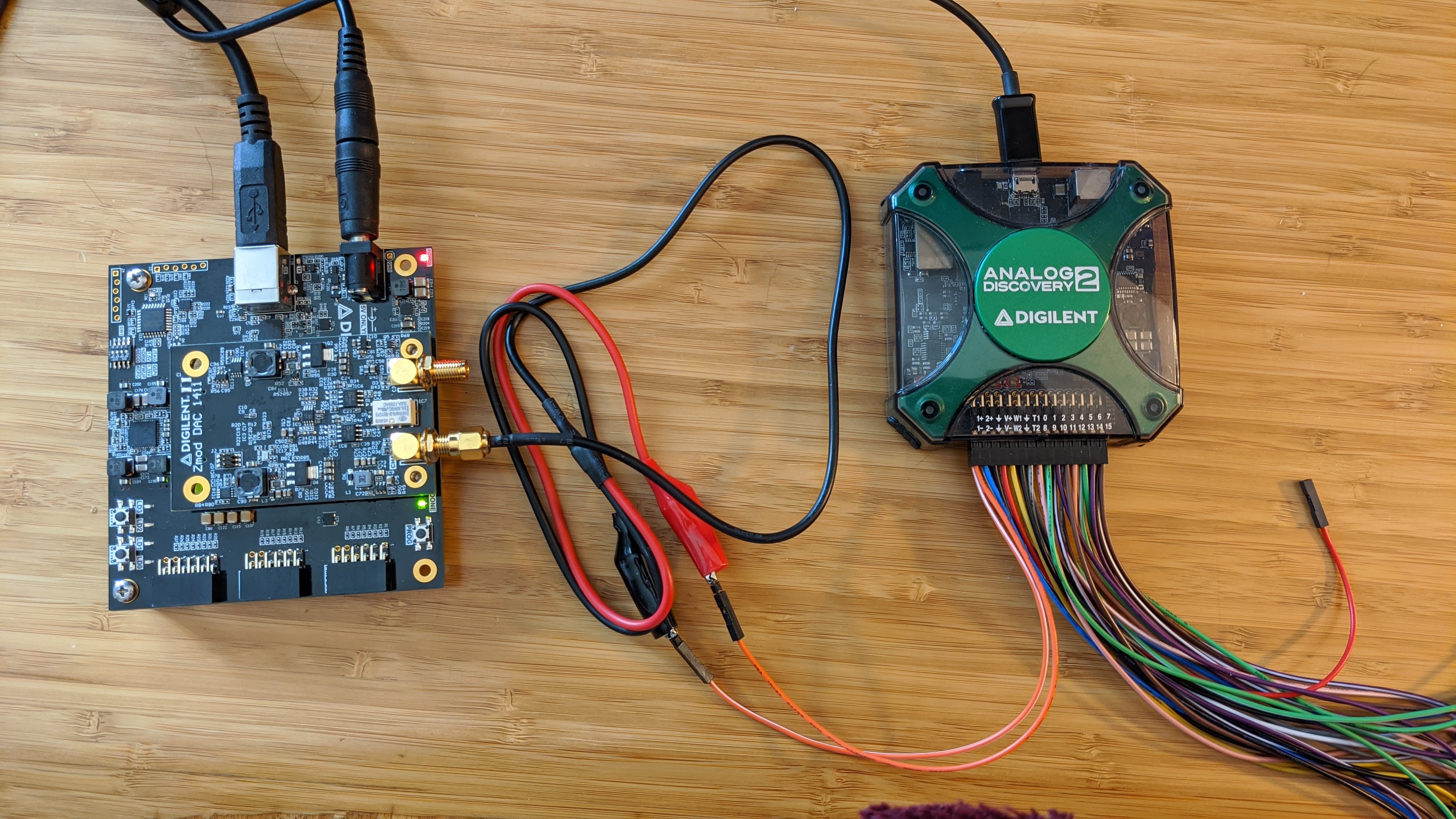
1. Connect the Analog Discovery 2 board to the host computer using a MicroUSB cable.
2. Connect the Zmod AWG 1411 to the USB104 A7 Syzygy port.
3. Connect the 5V power supply to the USB104A7. Plug the USB104 A7 into the PC using the USB A cable.
4. Screw the SMA to alligator clip cable into the Zmod AWG 1411, channel 1.
5. Connect the AD2 to the alligator clips as follows:
- 1+ to channel 1 red clip.
- 1- to channel 1 black clip.
Software Setup
Programming the FPGA
1. Download the release from the git repo releases. This includes the DPTI Console Application, the Vivado project, and the Xilinx SDK files with the prebuilt output products from Vivado.
2. Launch Xilinx SDK. Select the <release directory>/FPGA/sdk_workspace folder as the workspace.
3. Click File>Open Projects from File System. Click Directory and select the <release directory>/FPGA/sdk_workspace.
4. Select USB104A7_ZmodDAC_Demo, USB104A7_ZmodDAC_Demo_bsp, and design_1_wrapper_hw_platform_0. Click Finish. Xilinx SDK will import these projects and build them automatically.
5. Program the FPGA by clicking Xilinx>Program FPGA. Click Program.
6. To receive debug messages, open Tera Term and connect to the COM port associated with the USB104A7. Set the baud rate to 115200.
7. Program the Microblaze processor with the elf file. In the Project Explorer view, select the USB104A7_ZmodDAC_Demo project. Click Run>Run (Ctrl+F11).
8. Click Launch on Hardware (System Debugger) and then click OK.
Generating a waveform
The DPTI Console application accepts waveform csv files generated by the Digilent Waveforms application. These files list samples as weight values between -1 and 1 separated by newlines. This guide shows the steps to creating a custom waveform csv.
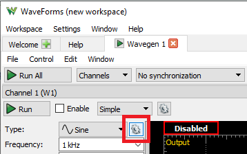
1. Open Digilent Waveforms and select the Wavegen.
2. Click the gear next to the Type dropdown menu and select New.
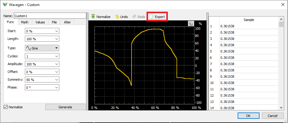
3. Generate a waveform using the tools provided. When finished click Export, then click Save. For ease of use, save this csv to the <release>/DPTI_App/DPTITransferWaveform folder.
Operating the Demo
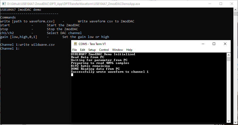
1. Run <release directory>/DPTI_App/DPTITransferWaveform/USB104A7_ZmodDACDemoApp.exe. The application will start up and connect to the USB104A7's DPTI port. If the program closes, there may be a connection issue.
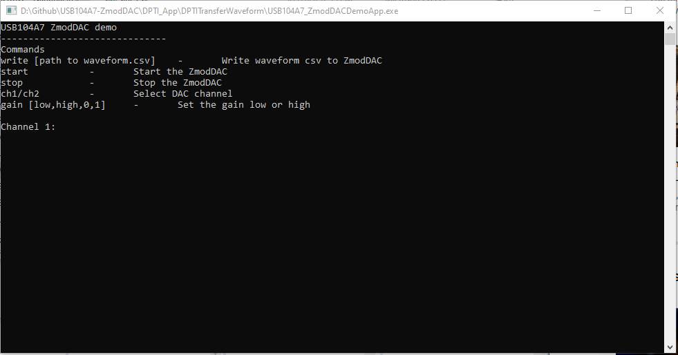
2. Type “write <path to waveform.csv>”. The Tera Term window should show debug information like in the picture below.
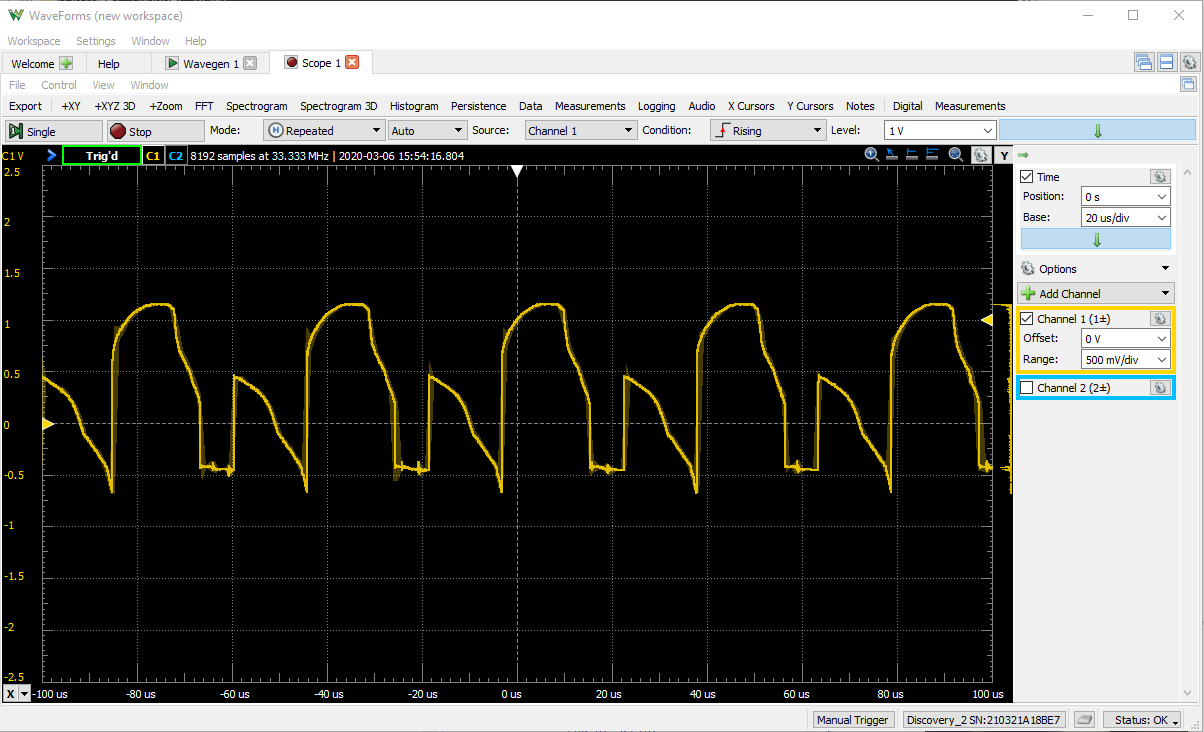
3. Type “start” to start the output on the Zmod AWG 1411.
4. In the Waveforms application, click Welcome>Scope.
5. Click Run to capture input from +1 and -1. Disable Channel 2 as it is not connected. You may need to zoom in and adjust the trigger to see the Zmod AWG 1411 output clearly.
Final Notes
For more guides and example projects for your USB104A7, please visit its Resource Center.
For more information about how to use the other Digilent products featured in this demo, please visit their respective Resource Centers:
Analog Discovery 2, Zmod AWG.
For technical support, please visit the Digilent Forums.