USB104 A7 Zmod Scope 1410 Demo
Overview
This project demonstrates the implementation of a Zmod Scope 1410 on the USB104 A7.
Description
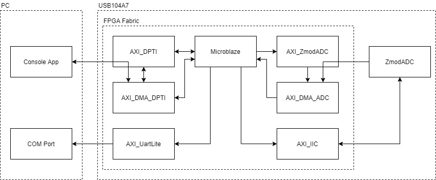
The simplified block diagram of the system implemented for this demo is shown below:
A console application is used to communicate with the USB104 A7. A typical application would be to arm the Zmod Scope 1410 with a specified trigger and store the resulting waveform to a file. The process of an arm operation on channel 1 is as follows:
1. Run application and program device.
2. Send a trigger level command to device using the application. “level 1.0”
- Triggerlevel opcode (4) or'ed with channel 1 (1«16) is sent over DPTI, followed by the value
3. Send an arm command to device along with a file name to save to. “arm waveform.csv”
- Arm opcode (1) or'ed with channel 1 (1«16) is sent over DPTI.
- The application then requests a buffer of default length 0x3FFF from the DPTI device. It will wait until data is received before continuing.
4. When the trigger occurs data is acquired from the Zmod Scope 1410 and sent to the channelbuffer through DMA.
5. Channelbuffer is then sent to the PC application over DPTI and saved to the specified CSV file.
The IPs instantiated in the design and their functionality are described below:
- ZmodADC1410 Low Level Controller - initializes the Zmod Scope 1410 hardware and formats the input data according to the AD9648 ADC requirements.
- AXI_ZmodADC - An AXI interface to communicate with the ZmodADC Low Level Controller from a software environment. Sends data to the ZmodADC through DMA.
- AXI_DPTI - Initializes the DPTI interface. Sends and receives data from the DPTI interface through DMA.
- AXI_IIC - An I2C interface to communicate with the ZmodADC hardware.
- AXI_UARTLITE - A UART interface used to send debugging messages to a COM port on the PC.
Inventory
Hardware
-
- Including a USB A cable and 5V Power Supply
- NOTE: SW1 DDR voltage set to 1.5V
-
- Including a Micro USB cable
Software
- Vivado Design Suite 2019.1 with Digilent Board Support Files installed
- Follow the Installing Vivado, Xilinx SDK, and Digilent Board Files guide on how to install Vivado and Digilent Board Support Files.
-
- Used to read debug messages from the FPGA. Follow the Serial Terminal Emulator Guide for more information on installing and using Tera Term.
Skills
- Basic familiarity with Vivado
- This experience can be found by walking through our “Getting Started with Vivado” guide
- Basic familiarity with Digilent Waveforms
Downloads
Demo Setup
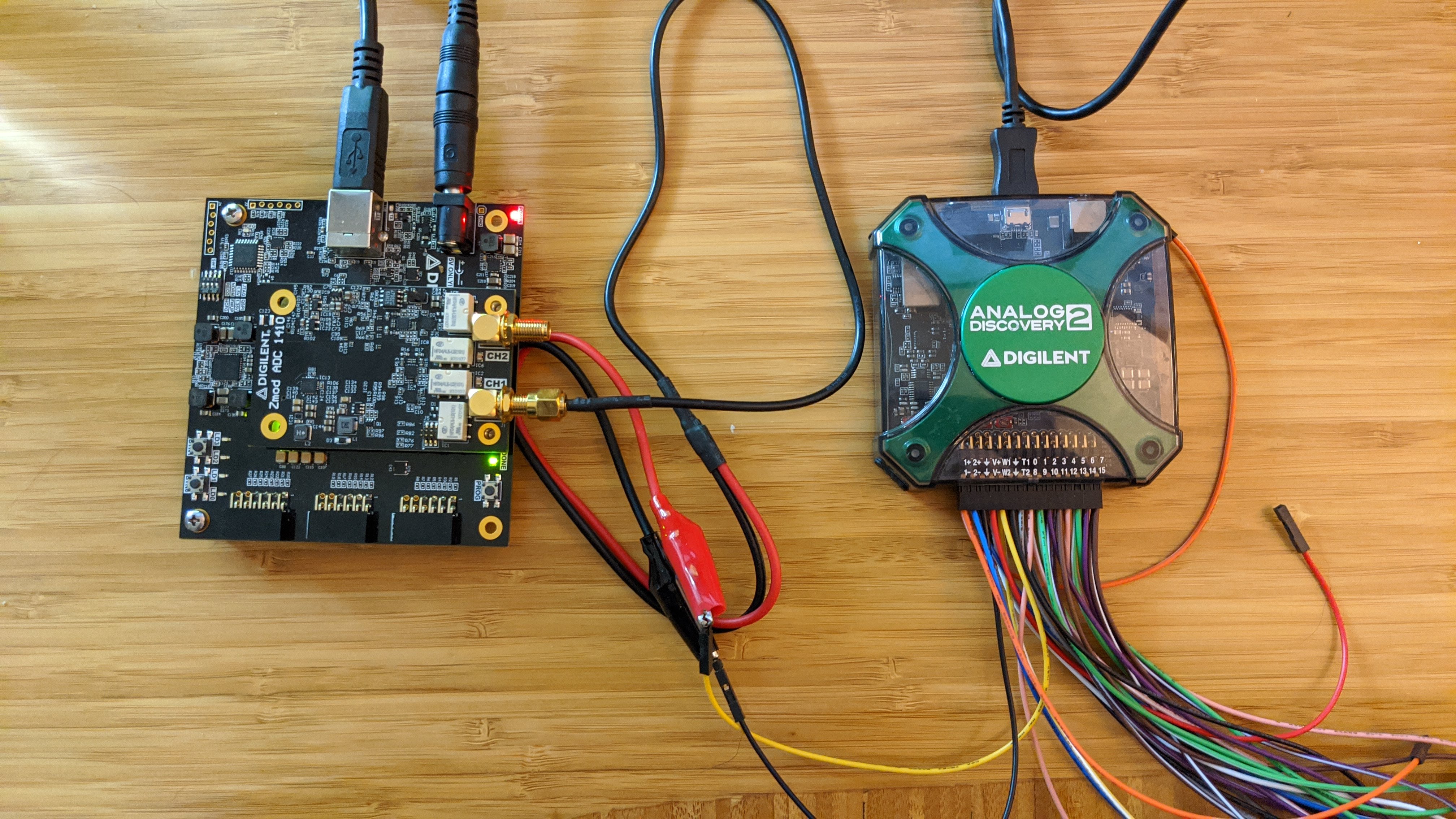
Hardware Setup
1. Connect the Analog Discovery 2 board to the host computer using a MicroUSB cable.
2. Connect the Zmod Scope 1410 to the USB104 A7 Syzygy port.
3. Connect the 5V power supply to the USB104A7. Plug the USB104 A7 into the PC using the USB A cable.
4. Screw the SMA to alligator clip cable into the Zmod Scope 1410, channel 1.
5. Connect the AD2 to the alligator clips as follows:
- W1 to channel 1 red clip.
- GND to channel 1 black clip.
Software Setup
Programming the FPGA
1. Download the release from the git repo releases. This includes the DPTI Console Application, the Vivado project, and the Xilinx SDK files with the prebuilt output products from Vivado.
NOTE: A precompiled bit+elf bit file has been included within the release/FPGA folder. This can be programmed to the FPGA using vivado hardware manager or Digilent Adept. Steps 2 through 8 can be skipped.
2. Launch Xilinx SDK. Select the <release directory>/FPGA/sdk_workspace folder as the workspace.
3. Click File>Open Projects from File System. Click Directory and select the <release directory>/FPGA/sdk_workspace.
4. Select USB104A7_ZmodADC_Demo, USB104A7_ZmodADC_Demo_bsp, and design_1_wrapper_hw_platform_0. Click Finish. Xilinx SDK will import these projects and build them automatically.
5. Program the FPGA by clicking Xilinx>Program FPGA. Click Program.
6. To receive debug messages, open Tera Term and connect to the COM port associated with the USB104A7. Set the baud rate to 115200.
7. Program the Microblaze processor with the elf file. In the Project Explorer view, select the USB104A7_ZmodADC_Demo project. Click Run>Run (Ctrl+F11).
8. Click Launch on Hardware (System Debugger) and then click OK.
Generating a waveform
1. Open Digilent Waveforms and select the Wavegen.
2. Select the type of waveform to generate and click Run.
Operating the Demo
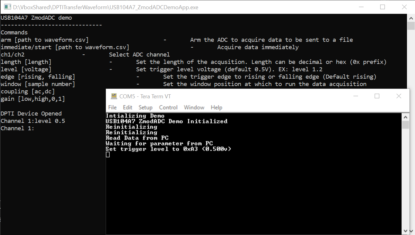
1. Run <release directory>/DPTI_App/DPTITransferWaveform/USB104A7_ZmodADCDemoApp.exe (USB104A7_ZmodADCDemoApp.o on Linux). The application will start up and connect to the USB104A7's DPTI port.
2. Type “level 0.5” to set the trigger level to 0.5V. The Tera Term window should show debug information like in the picture below.
3. Type “arm waveform.csv” to arm the Zmod Scope 1410. The program will arm the Zmod Scope 1410 and wait until the trigger occurs.
4. When the trigger occurs, the device will send the data to the PC and it will be saved to the waveform.csv file.

Final Notes
For more guides and example projects for your USB104 A7, please visit its Resource Center.
For more information about how to use the other Digilent products featured in this demo, please visit their respective Resource Centers:
Analog Discovery 2, Zmod Scope.
For technical support, please visit the Digilent Forums.