What is a Constraints File?
When programming an FPGA through software such as Xilinx's Vivado, you need to inform the software what physical pins on the FPGA that you plan on using or connecting to in relation to the HDL code that you wrote to describe the behavior of the FPGA.
In microcontroller land, this is very much like writing a register high or low on the microcontroller to turn an LED on or off, drive a clock, or to act as a data line. However, in a microcontroller many of these pins are “hard-wired” in the sense that you cannot relocate pins that are connected to a SPI controller to a physically different pin on the microcontroller. Generally speaking, it's just not an option.
This isn't the case for an FPGA; instead, you can create a hardware interface in HDL and then constrain the corresponding inputs and outputs on that interface to (essentially) whichever pins you want on the FPGA, making FPGAs very flexible for complex and custom designs.
However, this isn't to say that you can physically rearrange the PCB layout on the board through software. FPGA board manufacturers, such as Digilent, may physically connect some of the FPGA pins to certain on-board components within reason, such as routing some of the high speed transceiver lanes on the FPGA to an HDMI port rather than a Pmod host port or an on-board LED. You will not be able to change those physical locations. This doesn't stop you from assigning your clock pin in your code to be constrained to the clock pin that is inside an HDMI connector…you just may have a hard time physically accessing it (and using HDMI normally at the same time).
The constraints file that Xilinx's Vivado uses is called an XDC file (Xilinx Design Constraints file). Writing your own constraints file for inexperienced users can be very difficult since you are restricted by which FPGA pin is connected to which physical location on the board, and if you don't know where those are and what electrical property standard they support…it can become very frustrating very quickly.
Where can I find an XDC file?
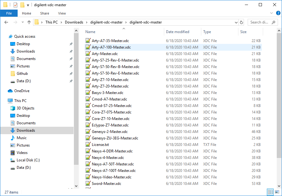
The master XDC files for all Digilent boards actively supported in Vivado can be found in the digilent-xdc repository on Github. Download this ZIP to get the latest versions of these files: digilent-xdc-master.zip
The master XDC file for your board lists all of the FPGA pins that are routed out to physical pins on the board; they are arranged by external component groups on the board for general convenience. All of the pins on the master XDC files are commented out so users will only need to uncomment the pins that they intend to use.
How do I get an XDC file into my project?
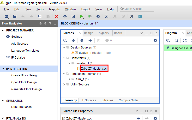
If your project doesn't contain the master Xilinx Design Constraint (XDC) file for your board, the dropdown below details how to add it. This file contains the constraints that your board places on designs using it - specific interfaces wired up to specific pins, clock frequencies, and FPGA bank voltages, for some examples. Click the dropdown below for a walkthrough of how to add this file to your project.
- Add a Master XDC File to a Vivado Project
-
Download and extract digilent-xdc-master.zip. This file includes all of the latest template XDC files released for Digilent's boards, which are available on Github in the digilent-xdc repository.
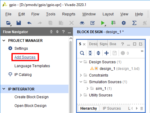
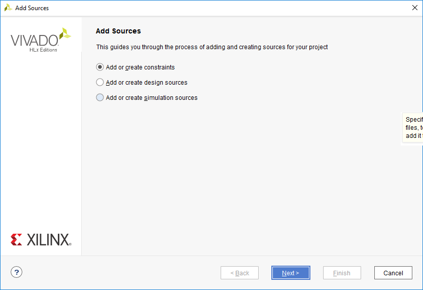
Returning to Vivado, click the Add Sources button in the Project Manager section of the Flow Navigator pane. This will launch a dialog that you can use to add a variety of types of source files to the project (or create new ones).
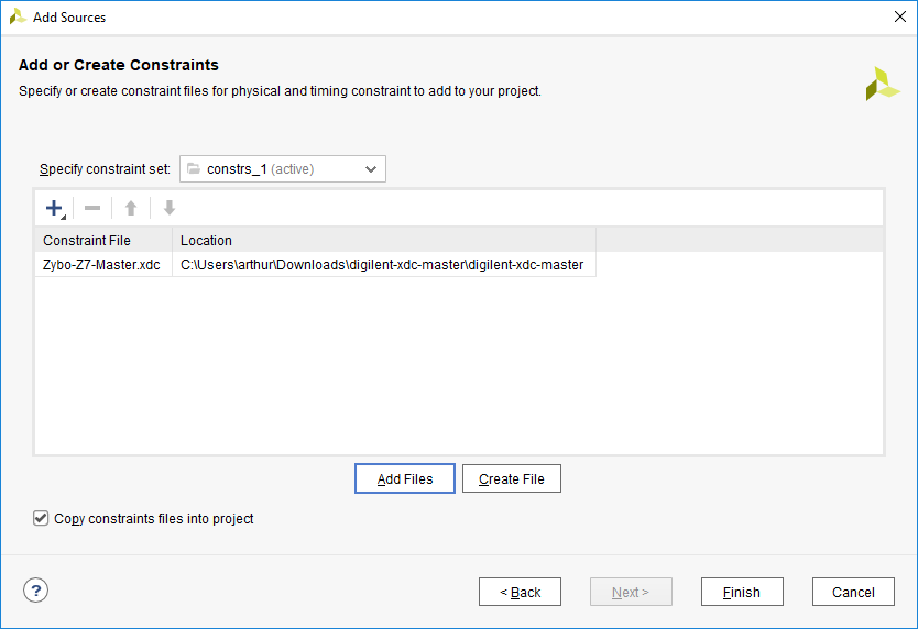
In the next screen, make sure that the constraint set specified (the one that the master XDC will be added to) is set to constrs_1, and that it is the active set. Click the Add Files button.
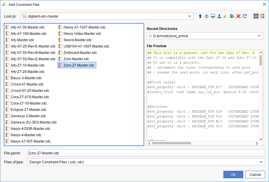
In the dialog that pops up, navigate to the folder that the digilent-xdc-master.zip file was extracted into. Highlight the XDC file for your board, then click OK to continue.
Back in the Add Sources dialog, make sure that your chosen constraint file appears in the table. Also, make sure that the Copy constraint files into project box is checked. If this box is unchecked, the file will be linked by your project, and any modifications made within the project will affect the version you downloaded. Since you may need to use this file again in other projects, copying the constraint file is recommended, so that you can always work from a fresh copy.
Click Finish to add the constraint file to your project.
What am I supposed to do with this XDC file anyway?
Aye, there's the rub; and likely why you clicked on this page in the first place.
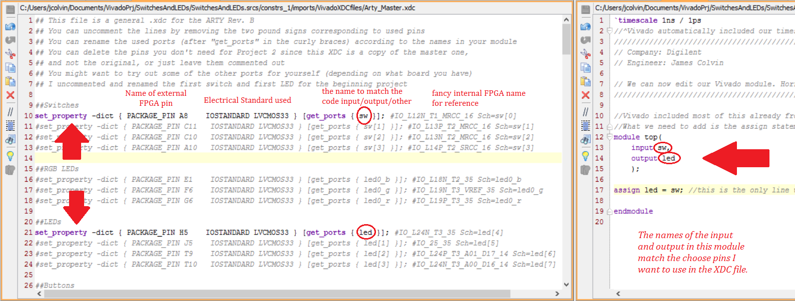
In general, the only portion of the XDC file you will change is the name of the external pin after get_ports that is surrounded by curly braces {} to match the input/output that you created in your main module code, as shown in the image below. You'll also need to make sure you uncomment the pins that you are using by deleting the first pound sign, #, in the line.

