Genesys 2 USB Device Demo
Overview
NOTE: This project can only be programmed using Vivado/SDK 2015.4
Features Used
| Not Used | Used | |
|---|---|---|
| 8 user switches | X | |
| 8 user LEDs | X | |
| 128×32 monochrome OLED display | X | |
| USB-UART Bridge | X | |
| 160-pin FMC LPC connector | X | |
| Micro SD card connector | X | |
| HDMI Sink and HDMI Source | X | |
| DisplayPort Source | X | |
| Audio codec w/ four 3.5mm jacks | X | |
| 5 user push buttons | X | |
| User EEPROM | X | |
| 10/100/1000 Ethernet PHY | X | |
| 512MiB 800Mt/s DDR3 Memory | X | |
| Serial Flash | X | |
| Four Pmod ports | X | |
| Pmod for XADC signals | X | |
| USB HID Host | X |
Description
The Genesys2 USB Device Demo project demonstrates the usage of the usb2device IP core on the Genesys2. . The behavior is as follows:
- The Genesys2 will act as a USB device, so the USB OTG port needs to be connected to a USB host.
- The USB IP should enumerate as a HID device (more specifically, as a mouse).
- BTNU, BTNL, BTND and BTNR will trigger interrupts if pressed. As a result, the Genesys2 will send HID reports that will cause the mouse pointer on the host to move in the corresponding direction (up, to the left, down or to the right).
- The UART terminal can be connected for debug purposes. It is configured to work at a baud rate of 115200 with 8 data bits, 1 stop bit, and no parity.
Prerequisites
Skills
- Basic familiarity with SDK
Hardware
- Genesys2 FPGA board
- Micro-USB cable
- Genesys2 Power Supply
Software
- Xilinx SDK 2015.4
Downloads
How to...
1. Download the Project
1.1) Download the project zip file which can be downloaded here. Once you have downloaded the project, unzip it in the location of your choosing.
1.2) If you want to generate the project in Vivado, continue to step 2. If you want to move straight to Xilinx SDK, skip to step 5.
2. Generate the Project
Generate the USB_Device_Demo project in the Projects folder by following this guide before continuing: How to Generate a Project from Digilent's Github. NOTE: This must be done in Vivado 2015.4
3. Build the Project
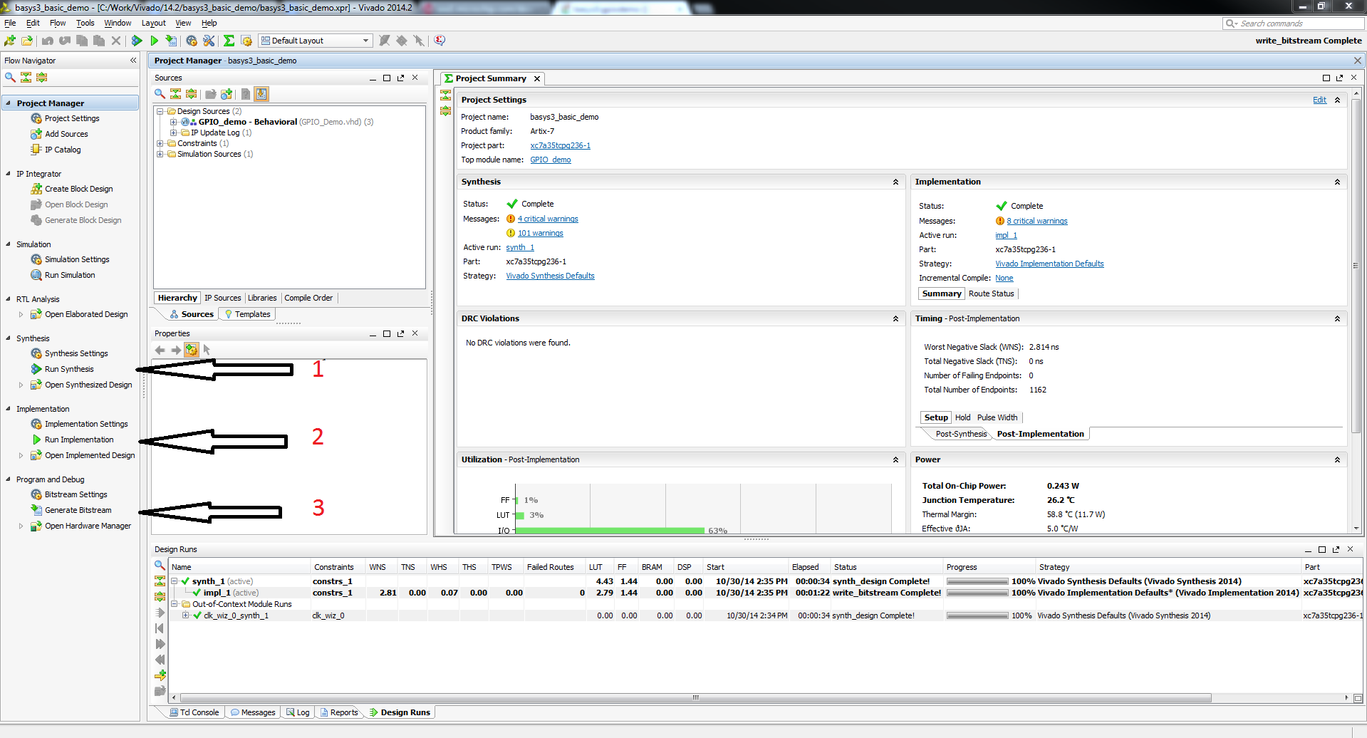
3.1) Click Generate Bitstream on the left hand menu towards the bottom. Vivado will run through both Run Synthesis and Run Implementation before it generates the bitstream automatically.
Note: If you want, you can click each step by itself in the order of Run Synthesis, Run Implementation and then Generate Bitstream.
4. Export to SDK
4.1) Export the microblaze project by going to File→Export→Export Hardware. Click the check box to Include the bitstream, and export it local to project. This will create a .sdk folder in your project directory. Afterwards, click File→Launch SDK. Both the exported location and workspace should be left as <Local to Project>. Click “OK” to launch Xilinx SDK.
4.2) Skip to step 6.
5. Open Xilinx SDK and create a workspace
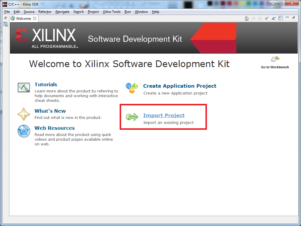
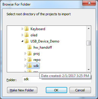
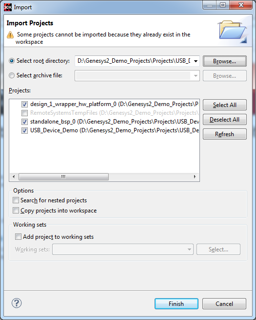
6. Import the SDK files
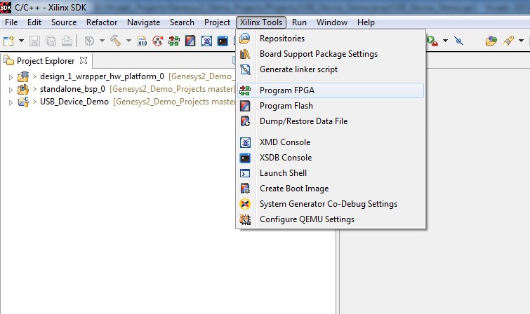
7. Program the FPGA
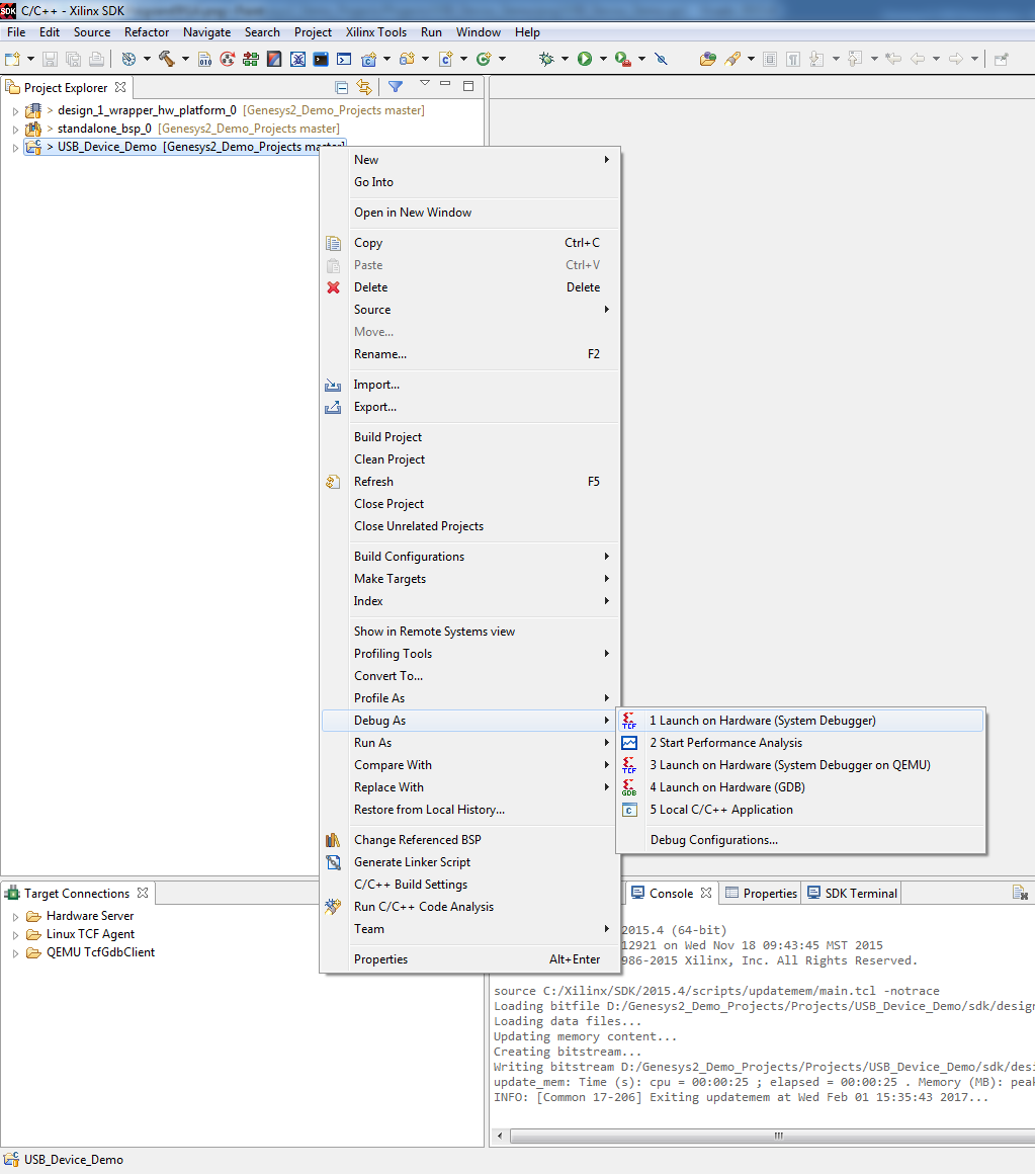
8. Program the Microblaze processor
9. Run the Project
This portion will help you run the demo and observe all its features.
9.2) Using the buttons
Pushbuttons BTNU, BTNL, BTND, BTNR will control the mouse pointer on the host PC.
9.3) Setting up UART communications
Plug a micro-USB cable into the plug labeled UART, and plug this into your computer.
You can use any serial terminal (Tera Term) to connect to the Genesys2 using 112500 baud rate, 8 data bits, no parity bit and 1 stop bit. This interface can be used in case status and debug functionalities are added.


