Pmod SF3 Reference Manual
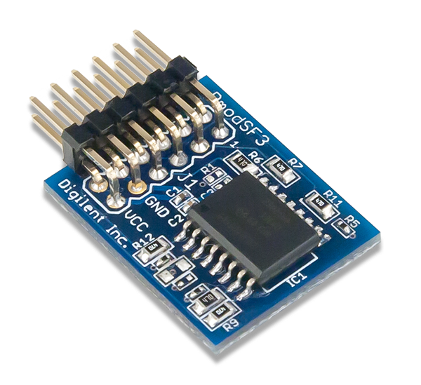
The Digilent Pmod SF3 (Revision A) provides 32 MB of serial Flash memory.
Download This Reference Manual
Features
- 32 MB serial NOR Flash memory
- Supports extended SPI protocol, dual I/O, and quad I/O
- Minimum 100,000 erase cycles per sector
- More than 20 years data retention
- 12-pin Pmod connector with SPI interface
- Follows Digilent Interface Specification Type 2A
Functional Description
The Pmod SF3 utilizes Micron's NOR Flash memory (N25Q256A) to provide easily accessed non-volatile memory to system boards. The data sheet can be found here.
Specifications
| Parameter | Min | Typical¹ | Max | Units |
|---|---|---|---|---|
| Recommended Operating Voltage | 2.7 | 3.3 | 3.6 | V |
| Maximum Supply Voltage | -0.6 | - | 4.0 | V |
| Power Supply Current² | - | - | 20 | mA |
| Power Supply Standby Current | - | - | 100 | µA |
| SPI Clock Speed³ | - | 25 | 104 | MHz |
| PAGE PROGRAM time (256 bytes) | - | 0.5 | 5 | ms |
| Sector ERASE time | - | 0.7 | 3 | s |
| Bulk ERASE time | - | 240 | 480 | s |
Note¹ - Data in the Typical Column uses VCC at 3.3V unless otherwise noted
Note² - During a read, program, or erase command
Note³ - When used with host boards that include series resistors on the Pmod ports the recommended max speed is 25MHz
Interfacing with the Pmod
The Pmod SF3 communicates with the host board via the SPI protocol. By bringing the Chip Select line logic level low voltage, users may issue a single byte instruction code to memory chip. A table of available commands can be found in the data sheet for the N25Q256A here starting on page 28.
The memory is byte-addressed with the range of 0x000000 to 0x1FFFFFF and is organized into 256 byte pages, 4 KB subsectors, and 64 KB sectors. The memory is written by using an Erase-Program cycle. The smallest programmable unit is one page and the smallest erasable unit is 1 subsector.
Users that wish to simply use the memory module without concerning themselves with the dual/quad input and output communication may use the example code and tutorials found on the Pmod SF3 Resource Center.
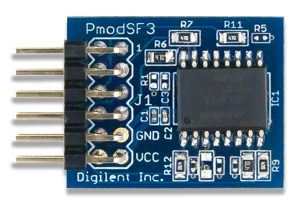
Pinout Description Table
| Pin | Signal | Description | Pin | Signal | Description | |
|---|---|---|---|---|---|---|
| 1 | ~CS | Chip Select | 7 | NC | Not Connected | |
| 2 | MOSI/DQ0 | Master-Out-Slave-In | 8 | RST | Reset | |
| 3 | MISO/DQ1 | Master-In-Slave-Out | 9 | W/DQ2 | Write Protect | |
| 4 | SCK | Serial Clock | 10 | HLD/DQ3 | Hold | |
| 5 | GND | Power Supply Ground | 11 | GND | Power Supply Ground | |
| 6 | VCC | Power Supply (3.3V) | 12 | VCC | Power Supply (3.3V) |
Any external power applied to the Pmod SF3 must be within 2.31V and 3.7V; it is strongly recommended the Pmod is operated at 3.3V.
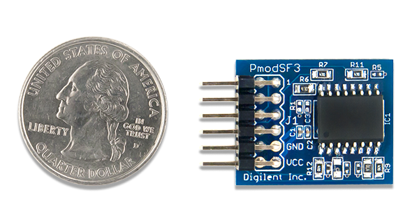
Physical Dimensions
The pins on the pin header are spaced 100 mil apart. The PCB is 1 inch long on the sides parallel to the pins on the pin header and 0.8 inches long on the sides perpendicular to the pin header.
Additional Information
The schematics of the Pmod SF3 are available here. Additional information about the Flash Memory module including communication modes and specific timings of the chip can be found by checking out its datasheet here.
More specific information about how to use the Pmod SF3 can be found by checking out the PmodSF3 Resource Center.
If you have any questions or comments about the Pmod SF3, feel free to post them under the appropriate section (“Add-on Boards”) of the Digilent Forum.