Pmod OLED Reference Manual
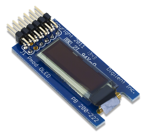
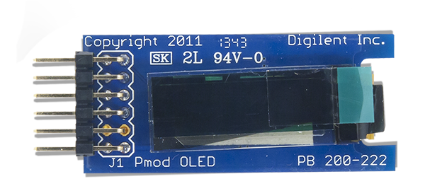
The Digilent Pmod OLED (Revision A) is an organic LED module with a 128×32 pixel display.

Download This Reference Manual
Features
- 128×32 pixel graphic OLED display
- Clock speeds of up to 10 MHz
- Internal display buffer
- 16 different brightness settings
- Small PCB size for flexible designs
- 12-pin Pmod connector with SPI interface
Functional Description
The Pmod OLED utilizes a Solomon Systech SSD1306 display controller to receive information from the host board and display the desired information on the OLED screen.
Interfacing with the Pmod
The Pmod OLED communicates with the host board via the SPI protocol. By driving and keeping the Chip Select (CS) line at a logic level low, users may send both commands and data streams to the display controller based on the state of the Data/Command (D/C) pin.
As a graphical display interface, users may light up any individual pixel on the OLED, display predefined characters, or even load bitmaps onto the screen. The OLED display has a specific power-up and power-down sequence to ensure the longevity of the device.
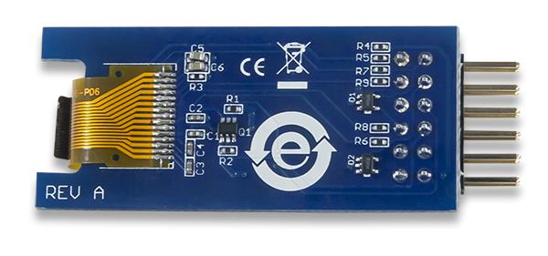
There are two field-effect transistors (FETs) that control the display’s two power supplies. The VDDC control toggles the power to the logic of the display and the VBATC control toggles the power to the OLED display itself. These two pins have pull-up resistors that turn off their respective power supplies when they're not being driven low to turn on the power supply.
Power-on Sequence
- Apply power to VDD.
- Send Display Off command.
- Initialize display to desired operating mode.
- Clear screen.
- Apply power to VBAT.
- Delay 100ms.
- Send Display On command.
Power-off Sequence
- Send Display Off command
- Power off VBAT
- Delay 100ms
- Power off VDD
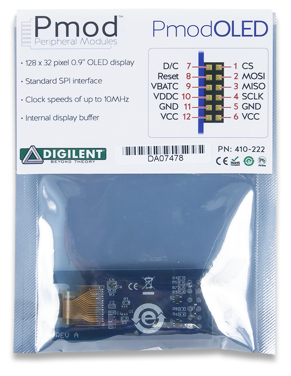
A pinout table of the Pmod OLED is provided below.
Pinout Description Table
| Header J1 | ||||||
|---|---|---|---|---|---|---|
| Pin | Signal | Description | Pin | Signal | Description | |
| 1 | CS | Chip Select | 7 | D/C | Data/Command Control | |
| 2 | MOSI | Master-Out-Slave-In | 8 | RES | Power Reset | |
| 3 | NC | Not Connected | 9 | VBATC | Vbat Battery Voltage Control | |
| 4 | SCK | Serial Clock | 10 | VDDC | Vdd Logic Voltage Control | |
| 5 | GND | Power Supply Ground | 11 | GND | Power Supply Ground | |
| 6 | VCC | Power Supply (3.3V) | 12 | VCC | Power Supply (3.3V) | |
Although users are welcome to create their own interface code for the Pmod OLED if they so desire, pre-constructed libraries that provide functions for initializing the display and rendering simple text and graphics onto the screen exist. They are available on the Pmod OLED Resource Center and can be used as-is or as a starting point for a more sophisticated graphics library.
Any external power applied to the Pmod OLED must be within 1.65V and 3.3V; however, it is recommended that Pmod is operated at 3.3V.
Physical Dimensions
The pins on the pin header are spaced 100 mil apart. The PCB is 1.8 inches long on the sides parallel to the pins on the pin header and 0.8 inches long on the sides perpendicular to the pin header.
Additional Information
The schematics of the Pmod OLED are available here. Additional information about the display controller including communication modes and specific timings of the chip can be found by checking out its datasheet here. Similarly, the datasheet for the display can be found here.
Example code demonstrating how to get information from the Pmod OLED can be found here.
If you have any questions or comments about the Pmod OLED, feel free to post them under the appropriate section (“Add-on Boards”) of the Digilent Forum.