Pmod MIC3 Reference Manual
The Pmod MIC3 is retired and no longer for sale in our store.
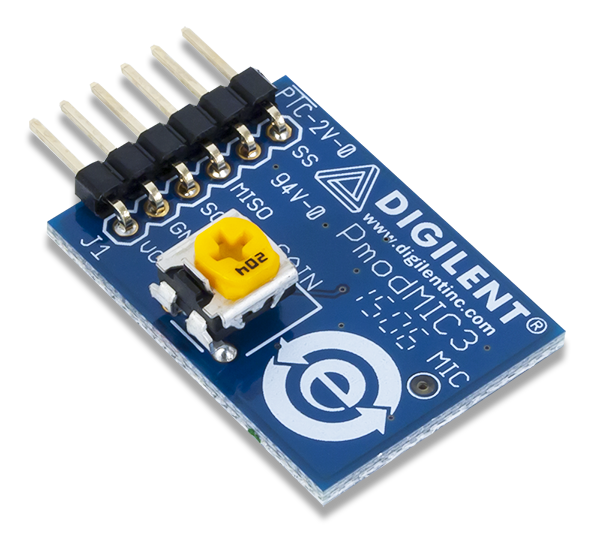
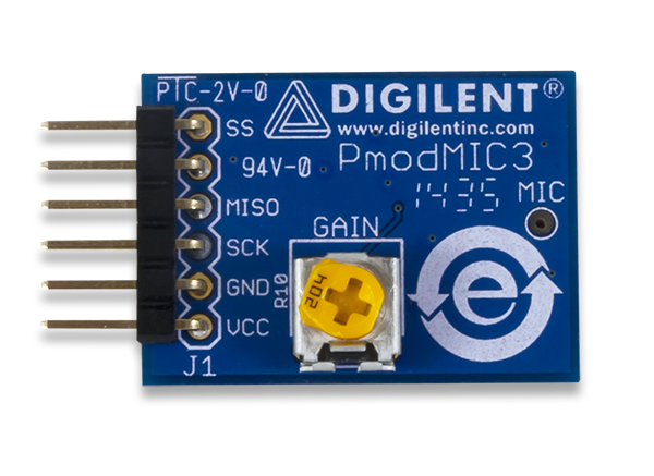
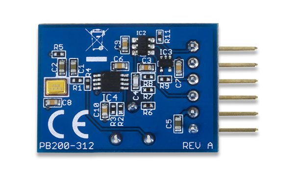
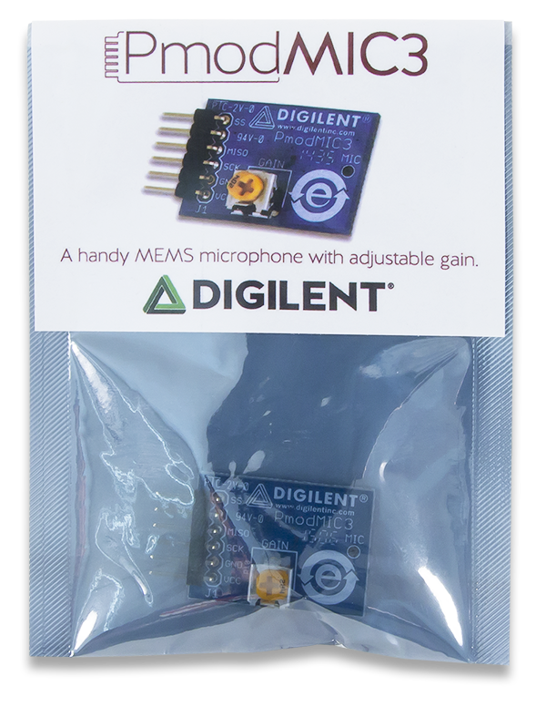
The Digilent Pmod MIC3 (Revision A) is small microphone module with a digital interface. With a Knowles Acoustics SPA2410LR5H-B MEMs microphone and Texas Instrument's ADCS7476 12-bit Analog-to-Digital Converter, you can capture your audio inputs with ease.
Download This Reference Manual
Features
- MEMS Microphone module with digital interface
- Transform audio inputs with 12-bit A/D converter
- Adjust incoming volume with on-board potentiometer
- Up to 1 MSPS of data
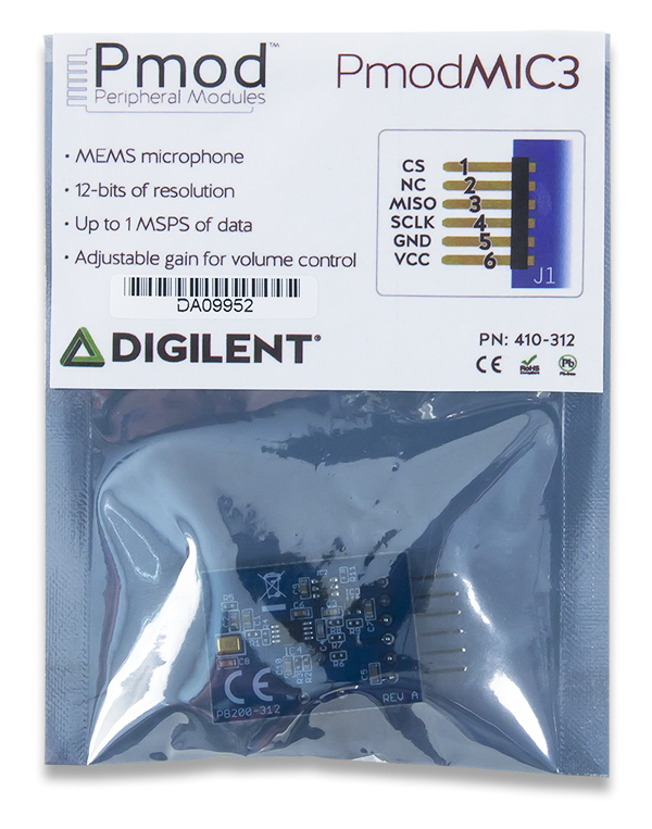
- 6-pin Pmod port with SPI interface
- Follows Digilent Pmod Interface Specification Type 2
Functional Description
The Pmod MIC3 is designed to digitally report to the host board whenever it detects any external noise. By sending a 12-bit digital value representative of frequency and volume of the noise, this number can be processed by the system board and have the received sound accurately reproduced through a speaker. The on-board potentiometer can be used to modify the gain from the microphone into the ADC.
Interfacing with the Pmod
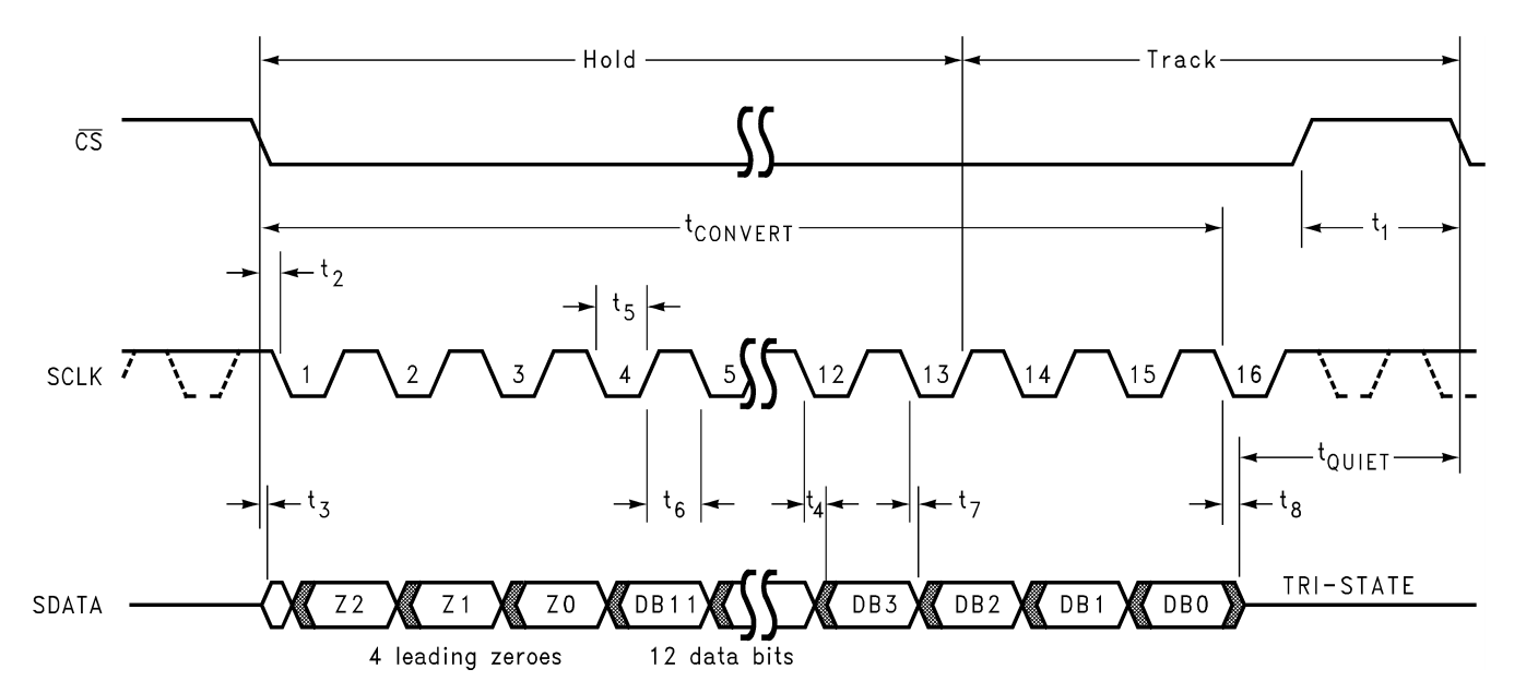
The Pmod MIC3 communicates with the host board via the SPI protocol. The 12 bits of digital data are sent to the system board in 16 clock cycles with the most significant bit first. For the ADC7476, each bit is shifted out on each falling edge of the serial clock line after the chip select line is brought low with the first four bits as leading zeroes and the remaining 12 bits representing the 12 bits of data. The datasheet for the ADC7476 recommends that for faster microcontrollers or DSPs that the serial clock line is first brought to a high state before being brought low after the fall of the chip select line to ensure that the first bit is valid.
Pinout Table Diagram
| Pin | Signal | Description |
|---|---|---|
| 1 | SS | Chip Select |
| 2 | NC | Not Connected |
| 3 | MISO | Master-In-Slave-Out |
| 4 | SCK | Serial Clock |
| 5 | GND | Power Supply Ground |
| 6 | VCC | Power Supply (3.3V/5V) |
The Pmod MIC3 is capable of converting up to 1 MSa per second of 12-bit data, making it an ideal Pmod to use in conjunction with the PmodI2S for an audio development application.
Any external power applied to the Pmod MIC3 must be within 3V and 5.5V to ensure that the on-board chips operate correctly; however, it is recommended that Pmod is operated at 3.3V.
Timing Diagram
A sample timing diagram taken from the ADCS7476 datasheet representing the data that will be received by the system board from the Pmod is provided below:
Physical Dimensions
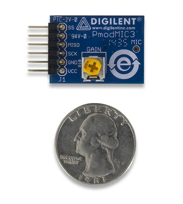
The pins on the pin header are spaced 100 mil apart. The PCB is 1.1 inches long on the sides parallel to the pins on the pin header and 0.8 inches long on the sides perpendicular to the pin header.
Additional Information
The schematics of the Pmod MIC3 are available here. Additional information about the ADC including communication modes and specific timings of the chip can be found by checking out its datasheet here. The datasheet for the microphone can be found here.
Example code demonstrating how to get information from the Pmod MIC3 can be found here.
If you have any questions or comments about the Pmod MIC3, feel free to post them under the appropriate section (“Add-on Boards”) of the Digilent Forum.

