Pmod LED Reference Manual
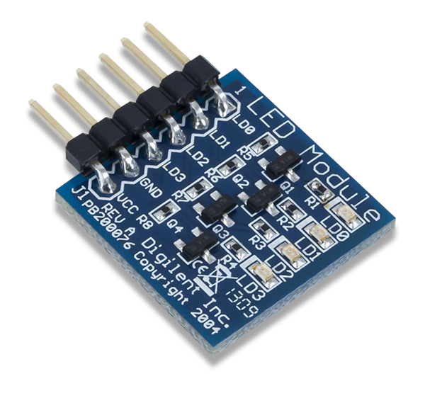
The Digilent Pmod LED (Revision A) contains 4 individual user LEDs that are driven through logic-level transistors.
Download This Reference Manual
Features
- 4 high-bright red LEDs
- Clearly visible logic level indicators
- Required driving current of < 1 mA
- 6-pin Pmod connector with GPIO interface
Functional Description
The Pmod LED utilizes logic-level transistors to light up four individual high-bright LEDs. Each LED can be turned on through the use of less than 1 mA of current, making this Pmod ideal for users needing small indicator lights.
Interfacing with the Pmod
The Pmod LED communicates with the host board via the GPIO protocol. A logic high level turns on the LED and a logic low signal turns off the LED .

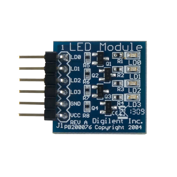
Pinout Description Table
| Pin | Signal | Description |
|---|---|---|
| 1 | LD0 | LED 0 |
| 2 | LD1 | LED 1 |
| 3 | LD2 | LED 2 |
| 4 | LD3 | LED 3 |
| 5 | GND | Power Supply Ground |
| 6 | VCC | Positive Power Supply |
It is recommended that the Pmod LED is operated at 3.3V.
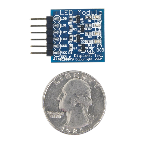
Physical Dimensions
The pins on the pin header are spaced 100 mil apart. The PCB is 0.8 inches long on the sides parallel to the pins on the pin header and 0.8 inches long on the sides perpendicular to the pin header.
Additional Information
The schematics of the Pmod LED are available here.
Example code demonstrating how to get information from the Pmod LED can be found here.
If you have any questions or comments about the Pmod LED, feel free to post them under the appropriate section (“Add-on Boards”) of the Digilent Forum.