Pmod DIP Reference Manual
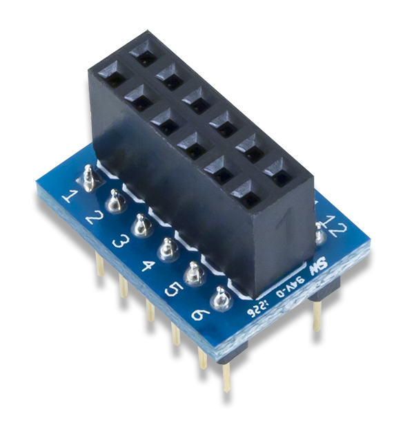
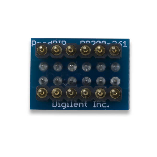
The Digilent Pmod DIP is a 12-pin Dual-Inline Package (DIP) that also includes a 2×6 female Pmod™ header, allowing users to easily separate and process any signals traveling to and from their 12-pin Pmod. It allows for easy use of Digilent Pmods in DIP sockets and solderless breadboards.
Download This Reference Manual
Features
- 12-pin dual inline package module
- 12-pin Pmod port for wire free breadboard connection
Functional Description
The Pmod DIP utilizes its 12 pass-through channels to route both digital and analog signals to and from the attached Pmod or other module. By being able to plug in the Pmod DIP into a solderless breadboard, external processing of the signals can be easily performed.
Interfacing with the Pmod
The Pmod DIP communicates with the host board via the GPIO protocol. As this is a pass-through module, all signals that are applied to each of the lanes will not be modified in any way.
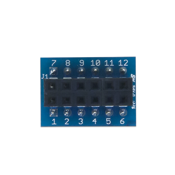
Pinout Description Table
| Pmod Header Pin | DIP Header | DIP Pin |
|---|---|---|
| 1 | J2 | 1 |
| 2 | J2 | 2 |
| 3 | J2 | 3 |
| 4 | J2 | 4 |
| 5 | J2 | 5 |
| 6 | J2 | 6 |
| 7 | J3 | 1 |
| 8 | J3 | 2 |
| 9 | J3 | 3 |
| 10 | J3 | 4 |
| 11 | J3 | 5 |
| 12 | J3 | 6 |
Any external power applied to the Pmod DIP must be within the limits that your system board and attached Pmod can handle.
Physical Dimensions
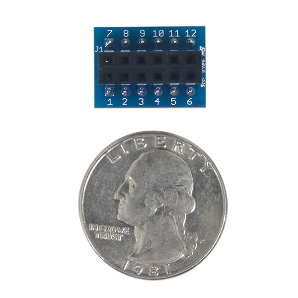
The pins on the pin header are spaced 100 mil apart. The PCB is 0.7 inches long and 0.5 inches wide.
Additional Information
The schematics of the Pmod DIP are available here.
As this is just a pass through module, no example code exists to properly demonstrate how to use the Pmod DIP.
If you have any questions or comments about the Pmod DIP, feel free to post them under the appropriate section (“Add-on Boards”) of the Digilent Forum.


