Pmod CON3 Reference Manual
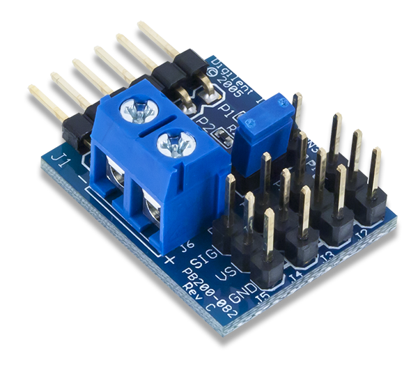
The Digilent Pmod CON3 (Revision C) can be used to easily interface with up to four small servo motors that deliver anywhere from 50 to 300 ounce/inches of torque such as those used in radio controlled airplanes or cars as well as some mechatronics projects.
Download This Reference Manual
Features
- Four standard 3-wire servo motor connectors
- Easily interface with Digilent system boards
- Flexible power delivery to servos
- 6-pin Pmod port with GPIO interface
Functional Description
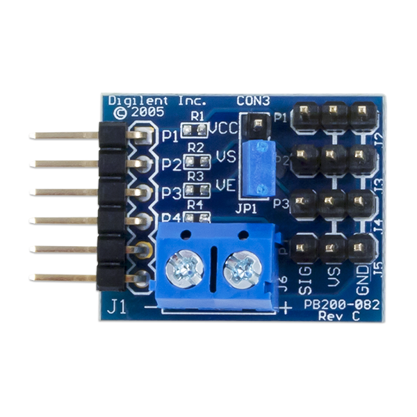
The Pmod CON3 allows any Digilent system board to easily interface with a standard 3-wire servo motor consisting of a signal, positive power supply, and ground power supply wires. The power supply can be sourced either from the system board or an external power source via screw terminals by selecting the appropriate setting on the jumper block.
Interfacing with the Pmod
The Pmod CON3 communicates with the host board via one of the four GPIO pins (the first four pins on the 1×6 header). As mentioned in the Functional Description, it is also possible to select how to power an attached servo motor by setting the shorting block in the appropriate jumper configuration.
| Table 1: Connector J1- Pin Descriptions as labeled on the Pmod | ||||
|---|---|---|---|---|
| Header J1 | Jumper JP1 | |||
| Pin Number | Description | Jumper Setting | Description | |
| 1 | Servo P1 | VCC | The voltage source for the servos comes from VCC and Ground | |
| 2 | Servo P2 | VE | The voltage source for the servos come from the + and - screw terminals | |
| 3 | Servo P3 | |||
| 4 | Servo P4 | |||
| 5 | Ground | |||
| 6 | VCC | |||
Table 1 Connector J1- Pin Descriptions as labeled on the Pmod
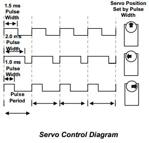
Standard servo motors use a potentiometer to adjust the angle at which their central shaft rotates to. In order to adjust the rotation angle, the motor generally needs to receive a “high” voltage pulse that ranges from 1 millisecond to 2 milliseconds, with 1.5 milliseconds as the “neutral” value. These values typically correspond to 0 degrees, 180 degrees, and 90 degrees, respectively, although depending on the manufacturer of the servo motor, these angles may vary. A signal that is either too narrow or too wide for a servo will cause the servo to try to go beyond its rotational range and can damage the servo. Always check the manufacturer’s instructions for a servo’s rotational range.
Because the pulse length is relatively long, any of the IO pins on a Digilent system board are capable of driving a servo motor. However, in order to have the servo motor maintain its given angle, a refresh pulse of the same (or new) angle will need to be provided to the servo motor periodically (20 milliseconds is a safe value). When using the Servo library available from Digilent, the refresh pulse and the pulse width are automatically taken care of allowing the user to simply give the desired angle for the servo motor to rotate to.
Physical Dimensions
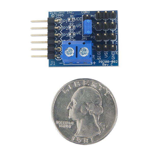
The pins on the pin header are spaced 100 mil apart. The PCB is 1.0 inches long on the sides parallel to the pins on the pin header and 0.8 inches long on the sides perpendicular to the pin header.
Additional Information
The schematics of the Pmod CON3 are available here.
More specific information about how to use the Pmod CON3 can be found by checking out our user guide. Example code demonstrating how to get information from the Pmod CON3 can be found here.
If you have any questions or comments about the Pmod CON3, feel free to post them under the appropriate section (“Add-on Boards”) of the Digilent Forum.

