Pmod GYRO Reference Manual
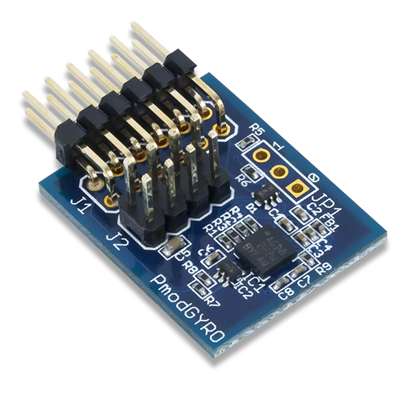
The Pmod GYRO (Revision A) utilizes ST L3G4200D gyroscope to provide motion sensing data on each of the three Cartesian axes. Users may configure both the resolution and filtering options for the measured data.
Download This Reference Manual
Features
- 3-axis MEMS digital gyroscope with high shock survivability
- Get angular momentum data with user selectable resolution (250/500/2000dps)
- Two customizable interrupt pins
- User configurable signal filtering
- Power-down and Sleep modes
- 12-pin Pmod port with SPI interface and additional I²C interface
Functional Description
The Pmod GYRO utilizes ST L3G4200D gyroscope to provide motion sensing data on each of the three Cartesian axes. Users may configure both the resolution and filtering options for the measured data.
Interfacing with the Pmod
The Pmod GYRO communicates with the host board via the SPI or I²C protocols. By driving the Chip Select (CS) line to a logic low voltage state, SPI mode is enabled. The first byte sent over SPI informs the on-board chip if a read or write command is going to be issued, if the register address should be incremented after a particular command has been completed, and the 5 bit address of the register that is to be written to.
An example timing diagram for SPI read and writes from the ST L3G4200D datasheet is provided below:

Correspondingly, if the CS line is left at a high voltage state by an internal pull-up resistor, the I²C mode of the Pmod GYRO is enabled. The on-board chip has two possible slave address in the form of 110100x where x is the voltage state of the Master-In-Slave-Out (MISO) pin on the SPI header. After the slave address and the read or write bit has been transmitted and the message was acknowledged, a 7-bit register address can then be transmitted. The most significant bit (the first bit of the 8-bit of the transfer) indicates if multiple bytes of information are to be transferred.
An example transfer scheme for a master device reading multiple bytes of data from the Pmod GYRO is provided below:
| Master | Start | Slave Address & Write Bit | Multi-byte bit & Register Address | Restart | Slave Address & Read Bit | ACK | ACK | NACK | Stop | ||||||
|---|---|---|---|---|---|---|---|---|---|---|---|---|---|---|---|
| Slave | ACK | ACK | ACK | Data | Data | Data |
Data is recorded and stored within the registers of the L3G4200D in degrees per second (dps). Correspondingly, a measured value of 360 dps is equivalent to 60 rpm. Users can retrieve data from the Pmod GYRO by following the provided code example.
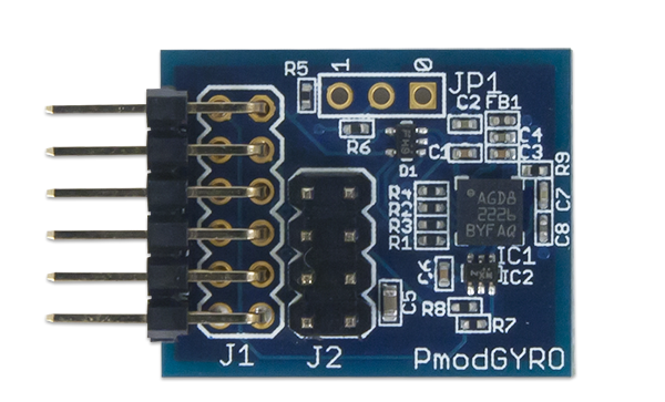
Pinout Description Table
| Header J1 | Header J2 | ||||||||
|---|---|---|---|---|---|---|---|---|---|
| Pin | Signal | Description | Pin | Signal | Description | Pin | Signal | Description | |
| 1 | ~CS | Chip Select | 7 | INT1 | Interrupt 1 | 1, 5 | SCL | Serial Clock | |
| 2 | MOSI | Master-Out-Slave-In | 8 | INT2 | Interrupt 2 | 2, 6 | SDA | Serial Data | |
| 3 | MISO | Master-In-Slave-Out | 9 | (NC) | Not Connected | 3, 7 | GND | Power Supply Ground | |
| 4 | SCLK | Serial Clock | 10 | (NC) | Not Connected | 4, 8 | VCC | Positive Power Supply (3.3V) | |
| 5 | GND | Power Supply Ground | 11 | GND | Power Supply Ground | ||||
| 6 | VCC | Positive Power Supply (3.3V) | 12 | VCC | Positive Power Supply (3.3V) | ||||
Any external power applied to the Pmod GYRO must be within 2.4V and 3.6V; however, it is recommended that Pmod is operated at 3.3V.
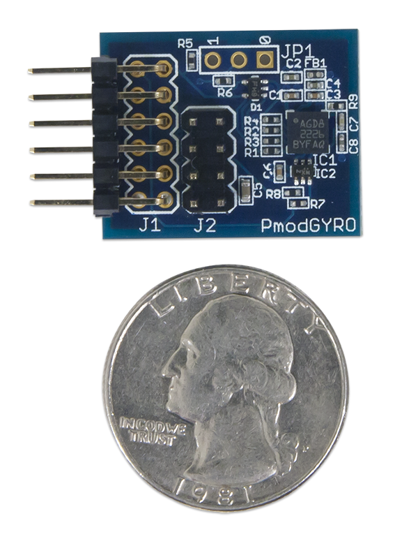
Physical Dimensions
The pins on the pin header are spaced 100 mil apart. The PCB is 1 inch long on the sides parallel to the pins on the pin header and 0.8 inches long on the sides perpendicular to the pin header.
Additional Information
The schematics of the Pmod GYRO are available here. Additional information about the gyroscope including communication modes and specific timings of the chip can be found by checking out its datasheet: ST L3G4200D datasheet.
Example code demonstrating how to get information from the Pmod GYRO can be found here.
If you have any questions or comments about the Pmod GYRO, feel free to post them under the appropriate section (“Add-on Boards”) of the Digilent Forum.