Creating a Custom IP core using the IP Integrator
Important!
This guide is out of date. The flow as described may be significantly different in recent versions of Vivado, especially those since Vitis was introduced in 2019.2.

Prerequisites
- Completed the Zybo Getting Started Guide - Have SDK installed
Tutorial
This demo will show how to build a basic PWM controller to manipulate on board LEDs using the processing system of the Zynq processor. We will be able to change the PWM window size from the IP graphic interface and then control the duty cycle in C written for the processor.
1. Open Vivado and create a new project
Open a new project as shown in the Zybo Getting Started Guide
Go to Tools→Create and package IP
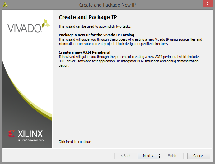
2. Create your custom IP project
2.1) Select Create a new AXI4 peripheral and click Next

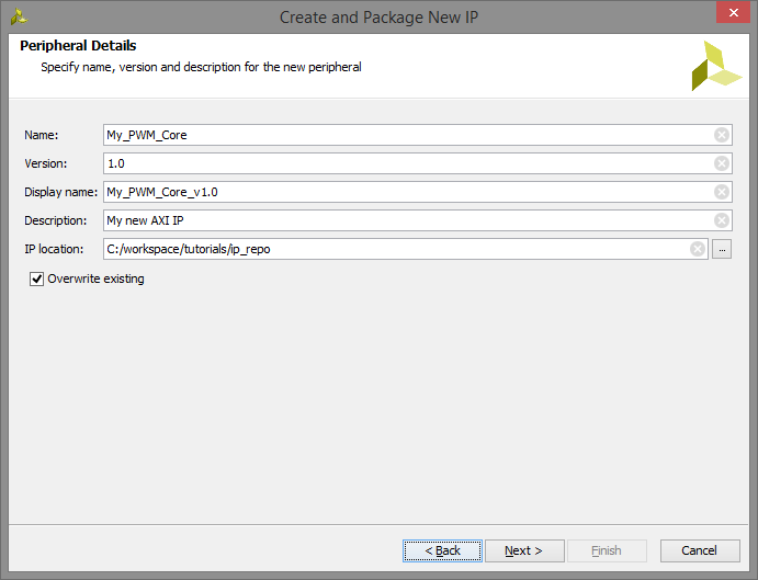
2.2) Input “My_PWM_Core” in the name field and click Next
2.3) No changes to the AXI interface are required, so click Next

2.4) Select Edit IP and click Finish

3. Designing the IP core
3.1) A new instance of Vivado will open up for the new IP core. Expand the top level file My_PWM_Core_v1_0. Then double-click on My_PWM_Core_v1_0_S00_AXI to open it in the editor.
4. Modifying My_PWM_Core_v1_0_S00_AXI
4.1)To allow for the user to change the maximum value of the PWM window in the top level, change this:
    // Users to add parameters here

    // User parameters ends
    // Do not modify the parameters beyond this line
To this:
    // Users to add parameters here
    parameter integer PWM_COUNTER_MAX = 1024,
    // User parameters ends
    // Do not modify the parameters beyond this line
4.2) To give the PWM signals a port out of the custom IP core, change this:
    // Users to add ports here

    // User ports ends
    // Do not modify the ports beyond this line
To this:
    // Users to add ports here
    output wire PWM0,
    output wire PWM1,
    output wire PWM2,
    output wire PWM3,
    // User ports ends
    // Do not modify the ports beyond this line
4.3) The following modification creates a counter that is 16-bits wide with a maximum of (2^16)-1, which will be more than enough for most applications. Scroll to the bottom of the file and change this:
    // Add user logic here

    // User logic ends
To this:
    // Add user logic here
    reg [15:0] counter = 0;

    //simple counter
    always @(posedge S_AXI_ACLK) begin
        if(counter < PWM_COUNTER_MAX-1)
            counter <= counter + 1;
        else
            counter <= 0;
    end

    //comparator statements that drive the PWM signal
    assign PWM0 = slv_reg0 < counter ? 1'b0 : 1'b1;
    assign PWM1 = slv_reg1 < counter ? 1'b0 : 1'b1;
    assign PWM2 = slv_reg2 < counter ? 1'b0 : 1'b1;
    assign PWM3 = slv_reg3 < counter ? 1'b0 : 1'b1;

    // User logic ends
Overall this module will write data into the slave registers from the processor. The simple counter will count till the max value and reset forever. Then each of the comparator statements checks if the current counter value is greater than the value stored in the slave registers and sets PWM high if the compare value is less than the current counter.
What we have accomplished:
– Parameterized the PWM window size with PWM_COUNTER_MAX
– Added ports so the higher level file can get the PWM signals
– Added a simple counter that counts from zero to PWM_COUNTER_MAX-1
– Added four asynchronous comparator signals that create the PWM signal
5. Modifying My_PWM_Core_v1_0
5.1) Double-click on My_PWM_Core_v1_0 to open it in the editor.
The following modifications add the ports for the PWM signals and the parameter up to the top HDL file. This will allow the GUI to change, connect, and modify the IP core.
5.2) Change this:
module My_PWM_Core_v1_0 #
(
    // Users to add parameters here

    // User parameters ends
    // Do not modify the parameters beyond this line
To this:
module My_PWM_Core_v1_0 #
(
    // Users to add parameters here
    parameter integer PWM_COUNTER_MAX = 128,

    // User parameters ends
    // Do not modify the parameters beyond this line
5.3) Then change this:
    // Users to add ports here

    // User ports ends
To this:
    // Users to add ports here
    output wire PWM0,
    output wire PWM1,
    output wire PWM2,
    output wire PWM3,
    // User ports ends
5.4) And this:
    // Instantiation of Axi Bus Interface S00_AXI
    My_PWM_Core_v1_0_S00_AXI # (
        .C_S_AXI_DATA_WIDTH(C_S00_AXI_DATA_WIDTH),
        .C_S_AXI_ADDR_WIDTH(C_S00_AXI_ADDR_WIDTH)
    ) My_PWM_Core_v1_0_S00_AXI_inst (
        .S_AXI_ACLK(s00_axi_aclk),
        .S_AXI_ARESETN(s00_axi_aresetn),
        .S_AXI_AWADDR(s00_axi_awaddr),
        .S_AXI_AWPROT(s00_axi_awprot),
        .S_AXI_AWVALID(s00_axi_awvalid),
        .S_AXI_AWREADY(s00_axi_awready),
        .S_AXI_WDATA(s00_axi_wdata),
        .S_AXI_WSTRB(s00_axi_wstrb),
        .S_AXI_WVALID(s00_axi_wvalid),
        .S_AXI_WREADY(s00_axi_wready),
        .S_AXI_BRESP(s00_axi_bresp),
        .S_AXI_BVALID(s00_axi_bvalid),
        .S_AXI_BREADY(s00_axi_bready),
        .S_AXI_ARADDR(s00_axi_araddr),
        .S_AXI_ARPROT(s00_axi_arprot),
        .S_AXI_ARVALID(s00_axi_arvalid),
        .S_AXI_ARREADY(s00_axi_arready),
        .S_AXI_RDATA(s00_axi_rdata),
        .S_AXI_RRESP(s00_axi_rresp),
        .S_AXI_RVALID(s00_axi_rvalid),
        .S_AXI_RREADY(s00_axi_rready)
    );
To this:
    // Instantiation of Axi Bus Interface S00_AXI
    My_PWM_Core_v1_0_S00_AXI # (
        .C_S_AXI_DATA_WIDTH(C_S00_AXI_DATA_WIDTH),
        .C_S_AXI_ADDR_WIDTH(C_S00_AXI_ADDR_WIDTH),
        .PWM_COUNTER_MAX(PWM_COUNTER_MAX)
    ) My_PWM_Core_v1_0_S00_AXI_inst (
        .PWM0(PWM0),
        .PWM1(PWM1),
        .PWM2(PWM2),
        .PWM3(PWM3),
        .S_AXI_ACLK(s00_axi_aclk),
        .S_AXI_ARESETN(s00_axi_aresetn),
        .S_AXI_AWADDR(s00_axi_awaddr),
        .S_AXI_AWPROT(s00_axi_awprot),
        .S_AXI_AWVALID(s00_axi_awvalid),
        .S_AXI_AWREADY(s00_axi_awready),
        .S_AXI_WDATA(s00_axi_wdata),
        .S_AXI_WSTRB(s00_axi_wstrb),
        .S_AXI_WVALID(s00_axi_wvalid),
        .S_AXI_WREADY(s00_axi_wready),
        .S_AXI_BRESP(s00_axi_bresp),
        .S_AXI_BVALID(s00_axi_bvalid),
        .S_AXI_BREADY(s00_axi_bready),
        .S_AXI_ARADDR(s00_axi_araddr),
        .S_AXI_ARPROT(s00_axi_arprot),
        .S_AXI_ARVALID(s00_axi_arvalid),
        .S_AXI_ARREADY(s00_axi_arready),
        .S_AXI_RDATA(s00_axi_rdata),
        .S_AXI_RRESP(s00_axi_rresp),
        .S_AXI_RVALID(s00_axi_rvalid),
        .S_AXI_RREADY(s00_axi_rready)
   );
6. Packaging the IP core
Now that we have written the core, it is time to package up the HDL to create a complete IP package.
6.1) Now click on Package IP in the Flow Navigator and you should see the Package IP tab. Select Compatibility and make sure “Artix7” and “Zynq” are present. If those are not there, you can add them by clicking the plus button. The Life Cycle does not matter at this point.

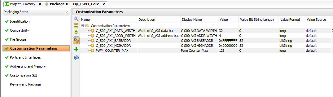
6.2) Select Customization Parameters and select the line for Merge Changes from Customization Parameters Wizard. This will add the PWM_COUNTER_MAX parameter from the top file under the hidden parameters folder.
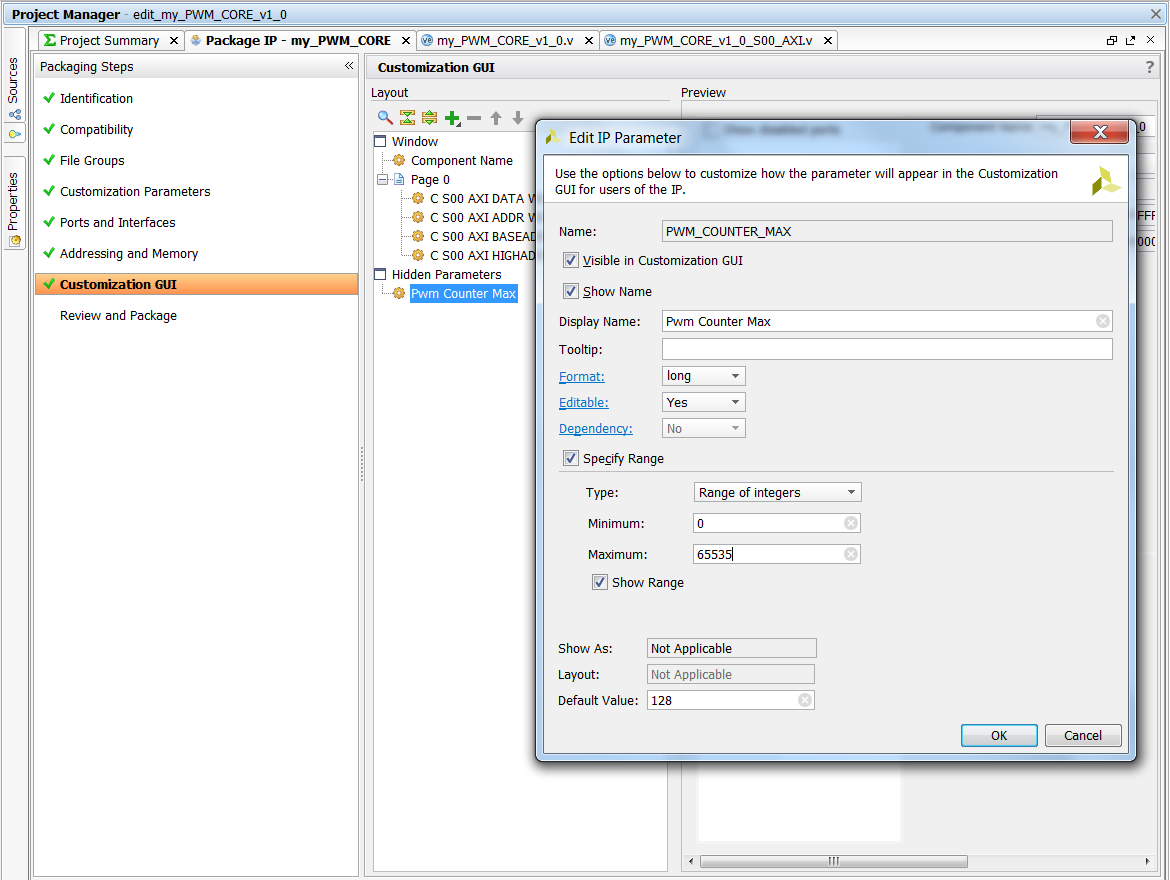
6.3) Select Customization GUI. This is were we get to change our graphical interface. One problem, there is not a window for our parameter. Right-click Pwm Counter Max and select Edit Parameter…. Check the box next to Visible in Customization GUI. Check the Specify Range box. Select Range of Integers from the Type drop-down menu. Since we have a max value of (2^16)-1 = 65535 and a min value of 0, this is not useful but whatever. Click Ok.
6.4) Drag the Pwm Counter Max into Page 0 to get it in the main page.
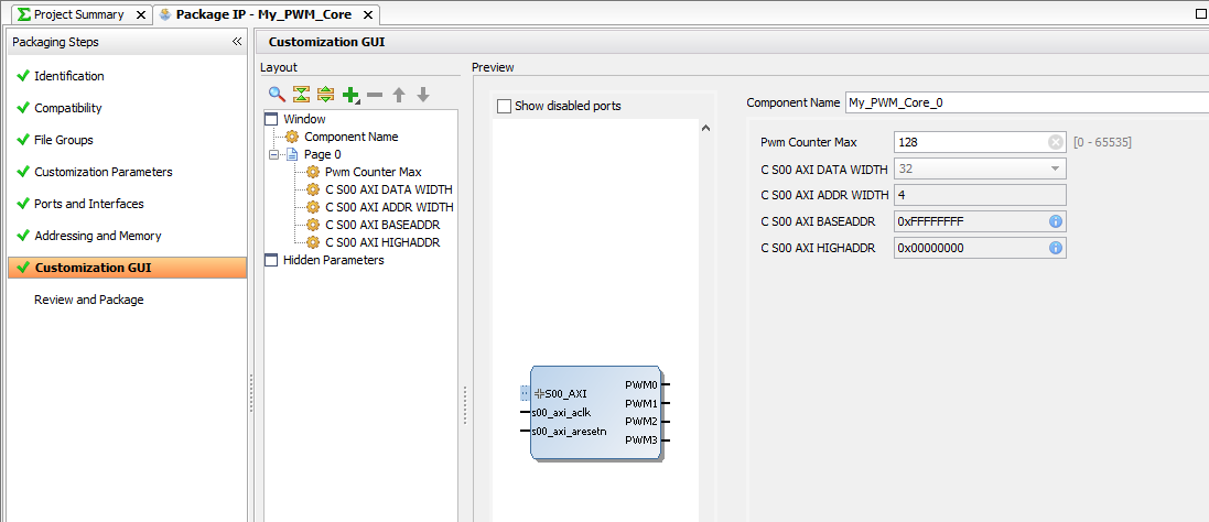
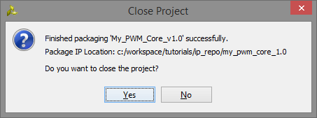
6.5) Now the core should be complete so select Review and Package and click the Re-package IP button.

6.6) A popup will ask if you want to close the project, Select Yes.
7. Create Zynq design
7.1) In the project manager page of the original window, click Create Block Design. This adds a block design to the project.
7.2) Use theAdd IP button to add the Zynq Processing System.

7.3) Use the
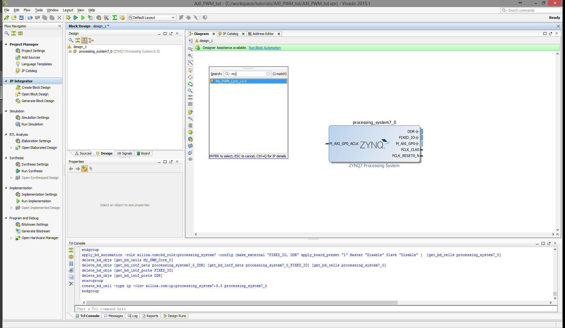
7.4) Run Block Automation.

7.5) Your design should look like this:
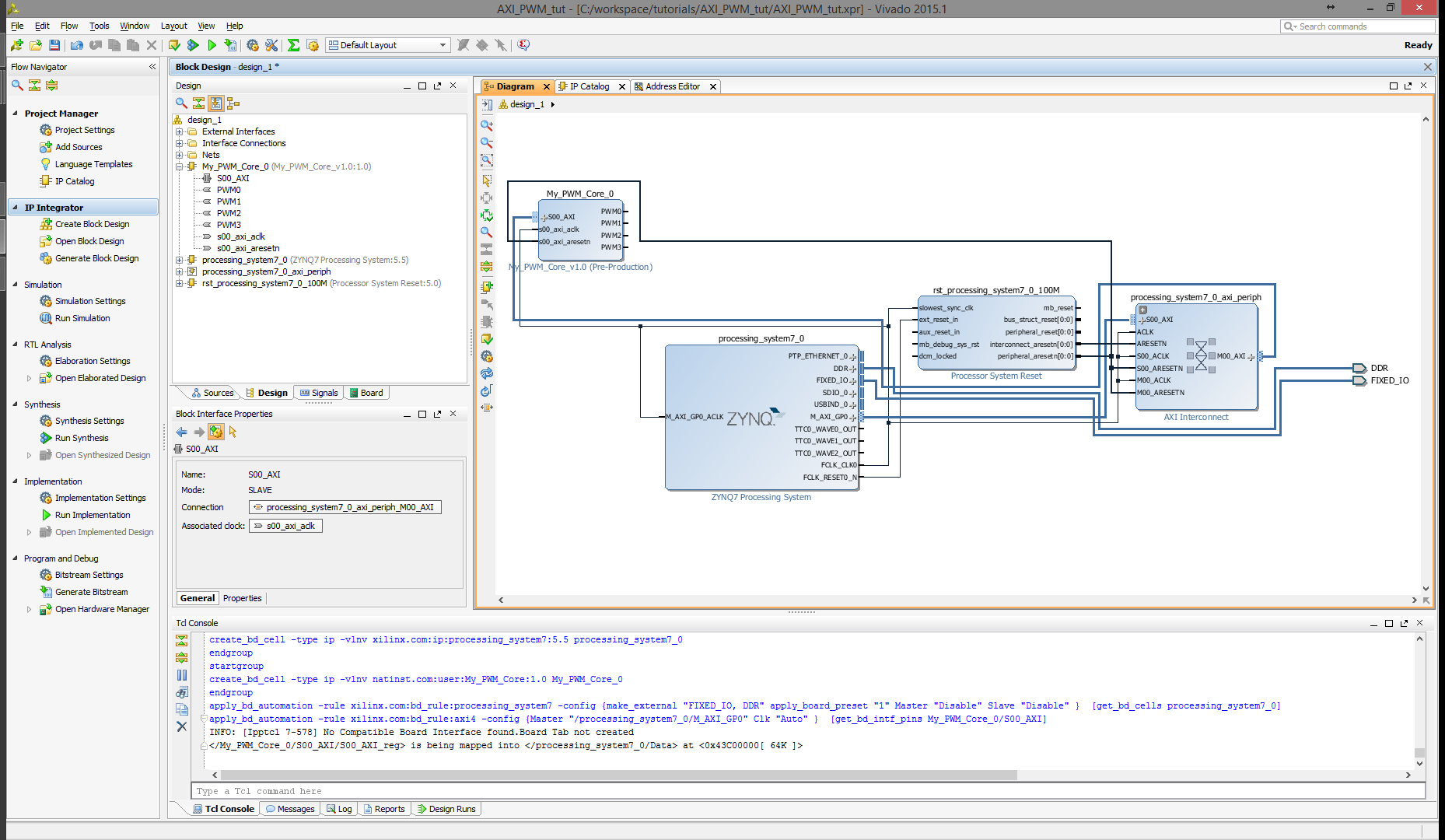
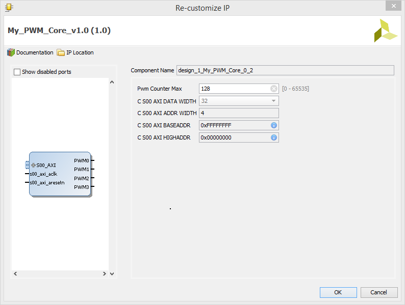
7.6) Double-click our PWM core to customize the parameter that we made earlier. Set the PWM Counter Max to 1024. and click OK.
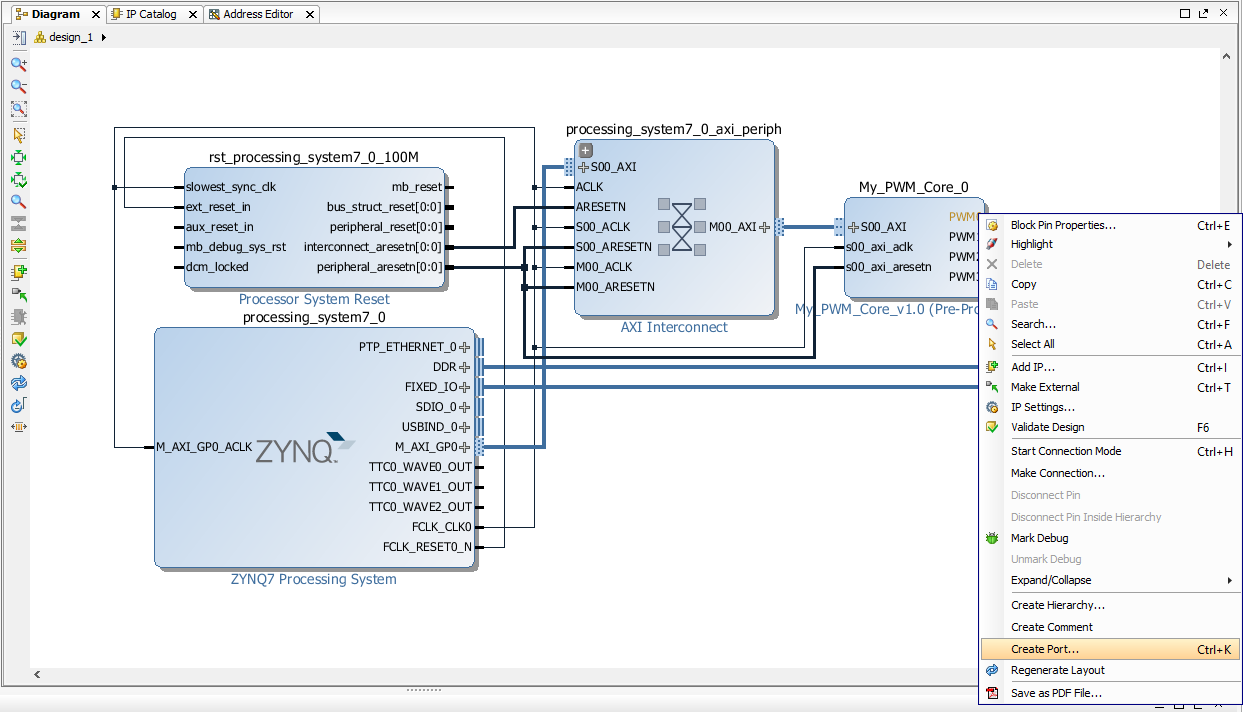
7.7) Right-click each of the PWM signals and select Create Port…
7.8) Click the button for Validate Design.

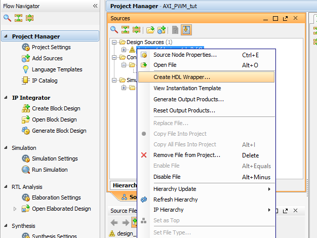
7.9) Click Project Manager, right-click the “design_1.db” file and Create HDL Wrapper…
7.10) Double-click design_1_wrapper.v to open it in the editor. Take note of the name for the PWM signals. Add the “Zybo_master.xdc” constraint file that can be downloaded here. Uncomment the lines of code for the LEDs in the xdc file and change this:
##IO_L23P_T3_35
set_property PACKAGE_PIN M14 [get_ports {led[0]}]
set_property IOSTANDARD LVCMOS33 [get_ports {led[0]}]

##IO_L23N_T3_35
set_property PACKAGE_PIN M15 [get_ports {led[1]}]
set_property IOSTANDARD LVCMOS33 [get_ports {led[1]}]

##IO_0_35
set_property PACKAGE_PIN G14 [get_ports {led[2]}]
set_property IOSTANDARD LVCMOS33 [get_ports {led[2]}]

##IO_L3N_T0_DQS_AD1N_35
set_property PACKAGE_PIN D18 [get_ports {led[3]}]
set_property IOSTANDARD LVCMOS33 [get_ports {led[3]}]
To this:
##IO_L23P_T3_35
set_property PACKAGE_PIN M14 [get_ports PWM0]
set_property IOSTANDARD LVCMOS33 [get_ports PWM0]

##IO_L23N_T3_35
set_property PACKAGE_PIN M15 [get_ports PWM1]
set_property IOSTANDARD LVCMOS33 [get_ports PWM1]

##IO_0_35
set_property PACKAGE_PIN G14 [get_ports PWM2]
set_property IOSTANDARD LVCMOS33 [get_ports PWM2]

##IO_L3N_T0_DQS_AD1N_35
set_property PACKAGE_PIN D18 [get_ports PWM3]
set_property IOSTANDARD LVCMOS33 [get_ports PWM3]
7.11) Click Generate Bitstream. Building the bit file can take some time.
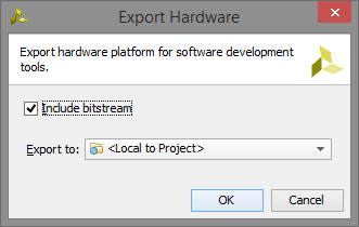
7.12) Export the hardware by going to File→Export→Export Hardware…
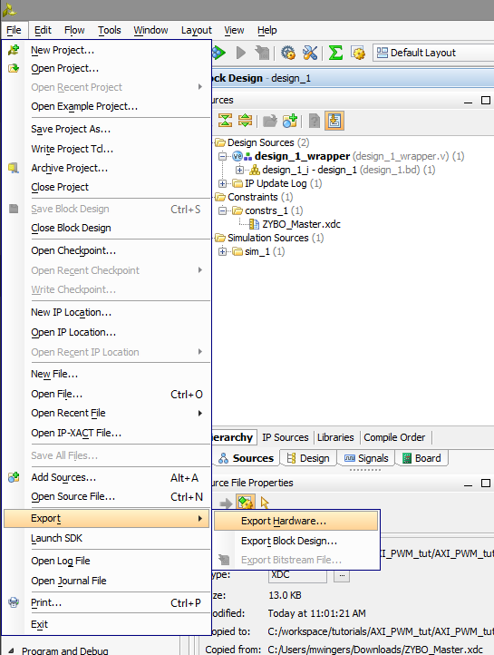
7.13) Check the box Include bitstream and click Ok
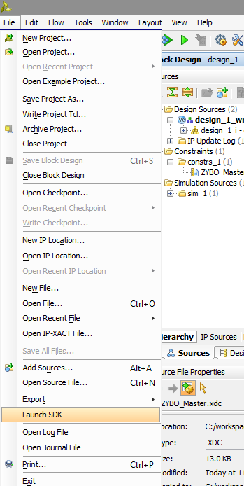
7.14) Select File→Launch SDK, and hit Ok on the window that pops up.
8. Programming in SDK
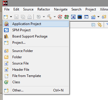
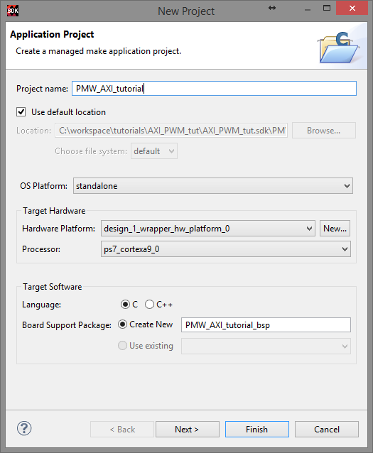
8.1) Create a new application project
8.2) Setup the window, click Next and Finish.
8.3) Expand the PWM_AXI_tutorial→src folder. Right-click the src folder and add a new file. Create a file named “main.c”.

8.4) Add the lines:
#include "xparameters.h"
#include "xil_io.h"

//#define MY_PWM XPAR_MY_PWM_CORE_0_S00_AXI_BASEADDR //Because of a bug in Vivado 2015.3 and 2015.4, this value is not correct.
#define MY_PWM 0x43C00000 //This value is found in the Address editor tab in Vivado (next to Diagram tab)

int main(){
    int num=0;
    int i;

    while(1){
        if(num == 1024)
             num = 0;
        else
             num++;

        Xil_Out32(MY_PWM, num);
        Xil_Out32((MY_PWM+4), num);
        Xil_Out32((MY_PWM+8), num);
        Xil_Out32((MY_PWM+12), num);

        for(i=0;i<300000; i++);
    }
}
8.5) To program the FPGA, Go to Xilinx Tools→Program FPGA. To load the SDK application onto the ZYBO, expand PWM_AXI_tutorial→binaries and right-click on “PWM_AXI_tutorial.elf” and select Run As→Launch on Hardware (GDB).

9. Celebrate!
Now the 4 LEDs on the ZYBO will be pulsing. Lean back in your chair and feel accomplished because you just created your own custom IP core.