Nexys Video DPTI Demo

Overview
The DPTI demo consists of a Vivado hardware project, an SDK project for the MicroBlaze processor, and a Windows application written in Visual Studio. Using these, the user can communicate with the Nexys Video's on-board DDR memory. Using a small Windows application, a file can be selected and sent to the Nexys Video via the USB PROG port at a specified memory address. After the transfer has been completed, it can then be read back and saved on the PC's hard drive at a specified location.
Features Used
| Not Used | Used | |
|---|---|---|
| 8 user switches | X | |
| 8 user LEDs | X | |
| 128×32 monochrome OLED display | X | |
| USB-UART Bridge | X | |
| 160-pin FMC LPC connector | X | |
| Micro SD card connector | X | |
| HDMI Sink and HDMI Source | X | |
| DisplayPort Source | X | |
| Audio codec w/ four 3.5mm jacks | X | |
| 6 user push buttons | X | |
| User EEPROM | X | |
| 10/100/1000 Ethernet PHY | X | |
| 512MiB 800Mt/s DDR3 Memory | X | |
| Serial Flash | X | |
| Four Pmod ports | X | |
| Pmod for XADC signals | X | |
| USB HID Host | X | |
| USB PROG/DPTI | X |
Prerequisites
Skills
- Basic familiarity with Vivado
- This experience can be found by walking through our “Getting Started with Vivado” guide
- Basic familiarity with Xilinx SDK
Hardware
- Nexys Video FPGA board
- Micro-USB cable
Software
- Vivado Design Suite 2015.4
- Newer/older versions can be used, but the procedure may vary slightly
- Xilinx SDK
- Digilent Adept 2 System
- Available for download here
Downloads
Tutorial
1. Generate the Project
1.1) Download the repository linked in the download section and place it in the location of your choosing.
1.2) Generate the DPTI project within the “Projects” folder by following this guide before continuing: How to Generate a Project from Digilent's Github
2. Build the Project
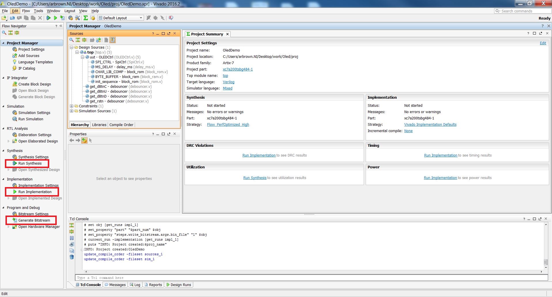
2.1) Click Generate Bitstream on the left-hand menu towards the bottom. Vivado will run through both Run Synthesis and Run Implementation before it generates the bitstream automatically.
Note: If you want, you can click each step by itself in the order of Run Synthesis, Run Implementation, and then Generate Bitstream.
3. Export to SDK
Export the MicroBlaze project by going to File>Export>Export Hardware. Click the check box to Include the bitstream, and export it to the hw_handoff folder.
4. Import the SDK files
In your project Explorer window on the left side, click File>Import then expand the General tab and click Existing Projects into Workspace. Navigate to the download folder, select the sdk folder, and click OK. In the Import window, click Finish to import the SDK project. Once the project has been imported, right-click on design_1_wrapper_hw_platform_0, select Change Harware Platform Specification, go to the hw_handoff, and then select the file found inside. Also, make sure to regenerate the BSP sources.
5. Program the FPGA
Click Xilinx Tools>Program FPGA and click Program. Xilinx SDK will then program the FPGA with a MicroBlaze bit file.
6. Run the SDK program
Right-click on the dpti_demo folder and click Run as>Launch on Hardware(GDB). The MicroBlaze program will be programmed onto your Nexys Video.
7. Running the Nexys Video DPTI Demo
7.1) Double-click on the DPTI_Transfer.exe file found in the DPTI_Transfer>Release folder. Check if the top left indicator is green and the text is DPTI * ON. If it is red, then the board is either not turned on or it is not connected properly.
7.2) Select Write to memory and enter a value for the address, which must be between 0x90000000 and 0xA0000000 since half of the 512MB DDR memory is reserved for the MicroBlaze processor (starting at 0x80000000) and the rest is available for this demo. This can be changed in the linker script.
Click on the Select file button and choose a file that you wish to transfer to the board. Video files, for example, are generally large and verifying their integrity after reading back is easy. Make sure to not exceed 256 MB.
After selecting the file, press the Write data button to send the file. You can follow the progress using a UART terminal (9600 BAUD).
When the transfer is finished, the top left box should be green with Upload complete written inside. Also, details regarding the transfer should appear on the right side of the window.
7.3) Now select the Read from memory option and use the same address as before. In this case, the user must also enter the amount of data that they want to transfer. You can copy the value from the Number of bytes field corresponding to the address used. After that, click on the Save file as button and provide a location and a file name. Make sure to enter the same termination that the file had when it was uploaded. Click on the Read data button to start the transfer. You can now check the file's integrity.
Multiple transfers can be performed in any direction and in any order; however, it is the user's responsibility to not write over existing data since neither the Windows application nor the SDK project keep track of the files which have already been written.


