NOTE: This project is currently under construction.
Nexys 4 XADC Demo

Overview
Description
This simple XADC Demo project demonstrates a simple usage of the Nexys 4's XADC port capability. The behavior is as follows:
- The 16 User LEDs increment from right to left as the voltage difference on the selected XADC pins gets larger.
- The two seven segment displays show the voltage difference on the AD11 pins in volts.
- sw0 and sw1 select which channel to read from
Features Used
| Not Used | Used | |
|---|---|---|
| 16 user switches | X | |
| 16 user LEDs | X | |
| Two tri-color LEDs | X | |
| 5 User Push Buttons | X | |
| Two 4-digit 7-segment displays | X | |
| 4 Pmod ports | X | |
| Pmod for XADC signals | X | |
| 12-bit VGA output | X | |
| USB-UART Bridge | X | |
| Serial Flash for Application Data | X | |
| USB HID Host With Mouse | X | |
| USB HID Host With Keyboard | X | |
| Micro SD card connector | X | |
| PWM audio output | X | |
| PDM microphone | X | |
| 3-axis accelerometer | X | |
| 16Mbyte CellularRAM | X | |
| Temperature sensor | X | |
| 10/100 Ethernet PHY | X |
Prerequisites
Hardware
- Nexys 4 FPGA board
- Micro-USB cable
- Wires and a voltage to measure
Software
- Vivado Design Suite 2016.4
- Newer versions can be used, but the procedure may vary slightly
- Nexys 4 Support Files
- These files will describe GPIO interfaces on your board and make it easier to select your FPGA board and add GPIO IP blocks.
- Follow the Wiki guide: Vivado Board Files for Digilent 7-Series FPGA Boards on how to install Board Support Files for
Downloads
Nexys 4 XADC Demo Project Repository – ZIP Archive GIT Repo
Download and Launch the Nexys 4 XADC Demo
Follow the Using Digilent Github Demo Projects Tutorial. This is an HDL design project, and as such does not support Vivado SDK, select the tutorial options appropriate for a Vivado-only design. As you will not need to set up your circuit to be measured until after the board is programmed, you do not need to return to this guide when prompted to check for extra hardware requirements and setup.
Using the Nexys 4 XADC Demo
This portion will help you run the demo and observe all its features.
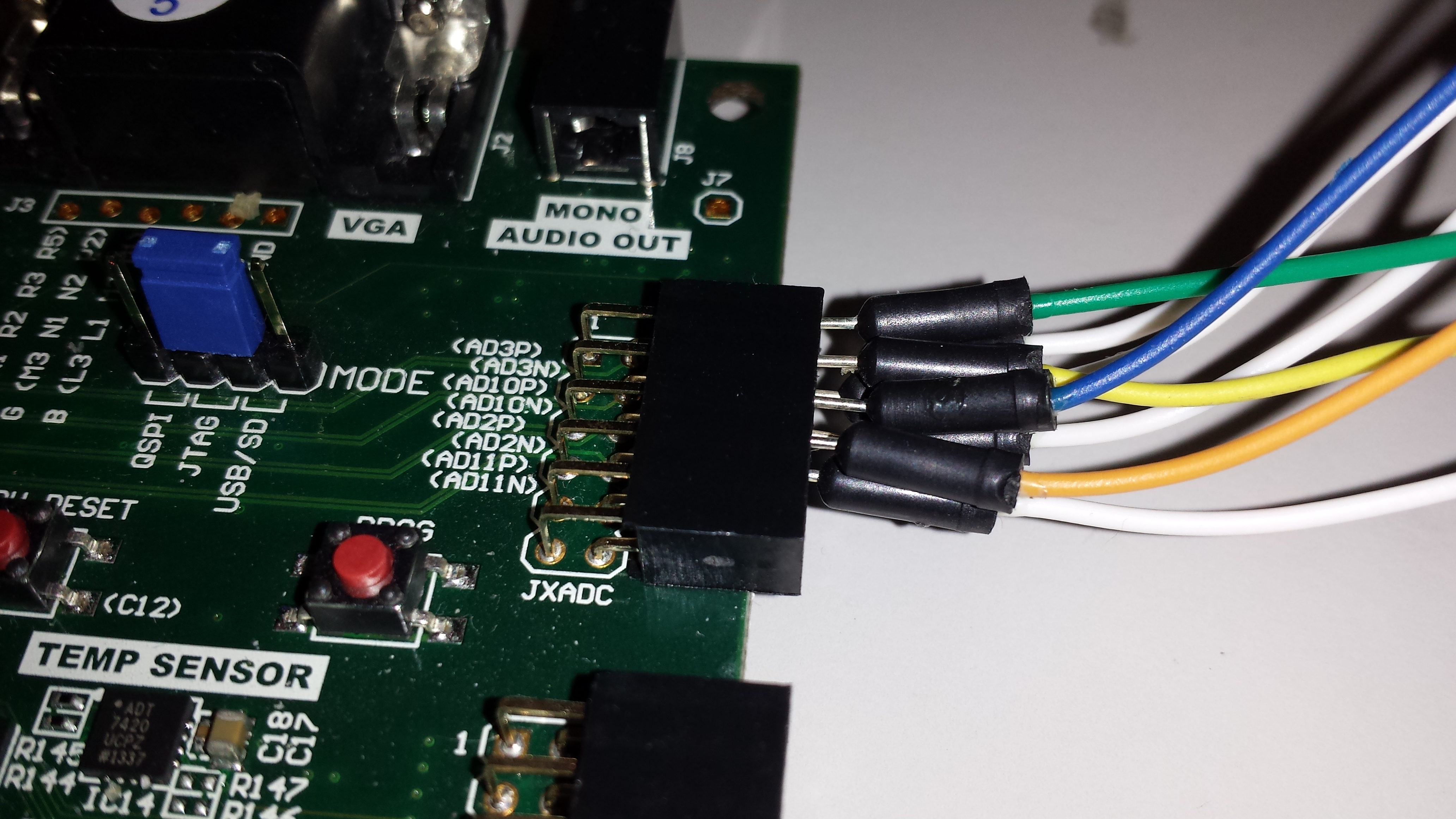
1. Applying a Voltage to the XADC Port
For this demo, the AD11P and AD11N pins are used on the JXADC header. We hooked up a signal generator to our pins. All of the other pins were grounded to avoid coupling.


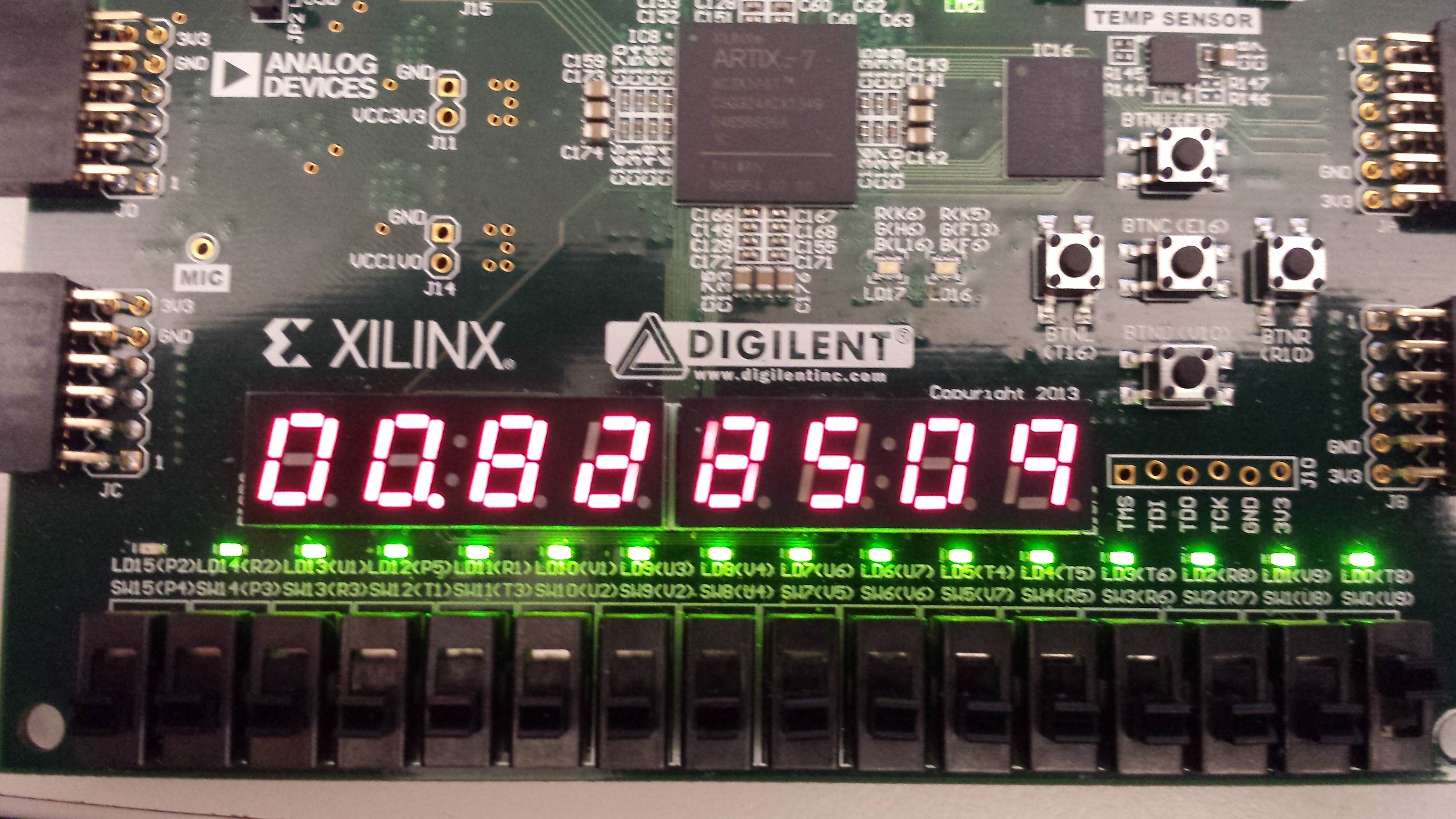
2. Seven Segment Display and LEDs
The 7-Segment display shows the current voltage across the selected xadc pins. The LEDs turn on from right to left as the input voltage increases.


3. Selecting a Channel
To display a different channel on the display and LEDs, select a channel from the table below and set switches sw0 and sw1 to the appropriate position.
| Channel Number | SW0 Position | SW1 Position |
|---|---|---|
| AD2 | Down (0) | Down (0) |
| AD3 | Up (1) | Down (0) |
| AD10 | Down (0) | Up (1) |
| AD11 | Up (1) | Up (1) |