Nexys 4 DDR Advanced I/O Demo ( Built-In Self-Test)

Overview
The Nexys 4 DDR was rebranded as the Nexys A7 starting with Revision D starting in 2018. Updated releases of this particular demo project, usable by all versions of both the Nexys 4 DDR and the Nexys A7 can be found in the Nexys A7 Resource center.
Description
The project represents the User Demo found on the Nexys4-DDR out-of-box and demonstrates usage of the VGA display in 1280×1024 mode, the Artix7 XADC, the Nexys4 DDR onboard ADT7420 Temperature Sensor on Two-Wire Interface, the ADXL362 Accelerometer on SPI Interface, the PS2 interface, the RGB LEDs, the ADMP421 Omnidirectional Microphone, Audio Output, the 16MB PSRAM Memory, user buttons, switches and LEDs.
The project was created under ISE 14.7 and then ported to Vivado 2016.4
The behavior is as follows:
The project connects to the VGA display in a 1280*1024 resolution and displays various items on the screen:
- a Digilent / Analog Devices logo
- a mouse cursor, if a Usb mouse is connected to the board when the project is started
- the audio signal from the onboard ADMP421 Omnidirectional Microphone
- a small square representing the X and Y acceleration data from the ADXL362 onboard Accelerometer.The square moves according the Nexys4 board position. Note that the X and Y axes on the board are exchanged due to the accelerometer layout on the Nexys4 board.The accelerometer display also displays the acceleration magnitude, calculated asSQRT( X^2 + Y^2 +Z^2), where X, Y and Z represent the acceleration value on the respective axes
- The FPGA temperature, the onboard ADT7420 temperature sensor temperature value and the accelerometertemperature value
- The value of the R, G and B components sent to the RGB LEDs LD16 and LD17
Other Features:
- The 16 Switches (SW0..SW15) are connected to LD0..LD15 except when audio recording is done
- Pressing BTNL, BTNC and BTNR will toggle between Red, Green and Blue colors on LD16 and LD17 Color sweeping returns when BTND is pressed. BTND also togles between LD16, LD17, none or both
- Pressing BTNU will start audio recording for about 5S, then the audio data will be played back on the Audio output. While recording, LD15..LD0 will show a progressbar moving to the right, while playing back, LD15..LD0 will show a progressbar moving to the left. Recorded audio data is stored in the onboard DDR2 memory.
Features Used
| Not Used | Used | |
|---|---|---|
| 16 user switches | X | |
| 16 user LEDs | X | |
| Two tri-color LEDs | X | |
| 5 User Push Buttons | X | |
| Two 4-digit 7-segment displays | X | |
| 4 Pmod ports | X | |
| Pmod for XADC signals | X | |
| 12-bit VGA output | X | |
| USB-UART Bridge | X | |
| Serial Flash for Application Data | X | |
| USB HID Host With Mouse | X | |
| USB HID Host With Keyboard | X | |
| Micro SD card connector | X | |
| PWM audio output | X | |
| PDM microphone | X | |
| 3-axis accelerometer | X | |
| 128MiB DDR2 | X | |
| Temperature sensor | X | |
| 10/100 Ethernet PHY | X |
Prerequisites
Skills
- Basic familiarity with Vivado
- This experience can be found by walking through our “Getting Started with Vivado” guide
Hardware
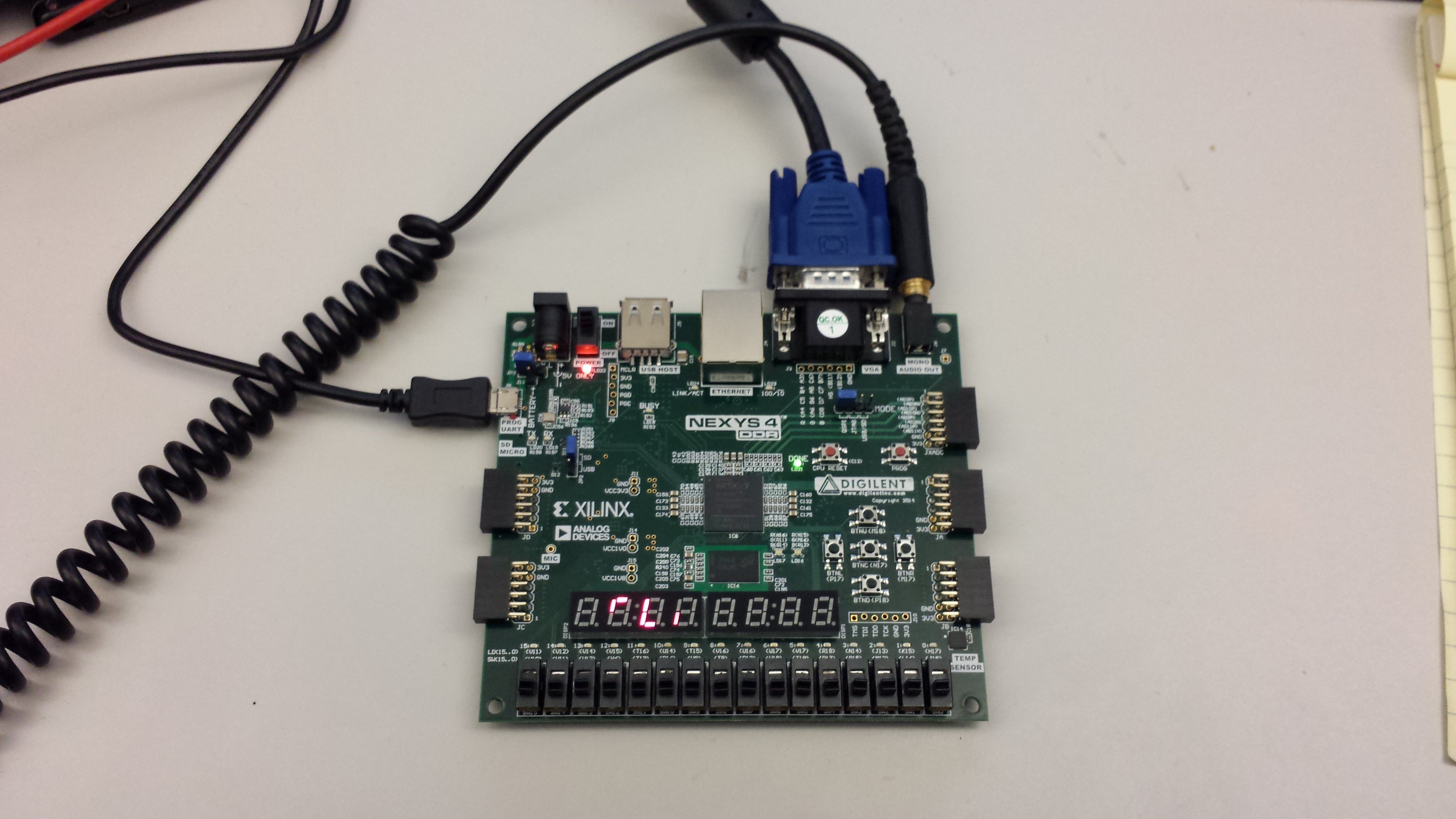
- Nexys 4 DDR FPGA board
- Micro-USB cable
- Headphones or speaker
- Monitor with a VGA cable
- USB mouse
Software
- Vivado Design Suite 2016.4
- Newer/older versions can be used, but the procedure may vary slightly
Downloads
Nexys 4 DDR OOB Project Repository – ZIP Archive GIT Repo
Download and Launch the Nexys 4 DDR Advanced User Demo
Follow the Using Digilent Github Demo Projects Tutorial. This is an HDL design project, and as such does not support Vivado SDK, select the tutorial options appropriate for a Vivado-only design. As you do not need to set up any of your additional hardware until after your board has been programmed, you do not need to return to this guide when prompted to check for extra hardware requirements and setup.
Using the Nexys 4 DDR Advanced User Demo
1. Using the Switches with LEDs
For this section, all the switches are tied to their corresponding LED. Every time a switch is toggled, the LED directly above it will toggle with it.


2. Seven Segment Display
The 7-Segment display runs a constant snake pattern. There is no way to change this pattern with the Nexys4-DDR I/O.
3. Tri-color LEDs and Push Buttons
The two tri-color LEDs are initially set to gradually change from red to green, then green to blue, then back to red. If the user pushes btnR, the LEDs are set to blue. If the user pushes btnC, the LEDs are set to green. If the user pushes btnL, the LEDs are set to red. Finally if the user pushes btnD, the LEDs return to their gradual change loop. If the user keeps pushing btnD, both LEDs will be isolated then both will be turned off.


4. Audio Recorder
If the user pushes btnU, an audio recording is started and data is taken from the omni-directional microphone. The data is stored into the DDR2 memory. While the recorder is recording, the LEDs will light up from left to right. After about five seconds, the audio will be read from DDR2 memory and played through the headphone jack (labeled mono audio out). LEDs will turn off from right to left.

5. VGA Output and Mouse Control
When the demo is connected to a VGA display, the following is displayed at a 1280×1024 resolution:
* A Digilent / Analog Devices logo
* A mouse cursor, if a Usb mouse is connected to the board when the project is started
* The audio signal from the onboard ADMP421 Omnidirectional Microphone
* A small square representing the X and Y acceleration data from the ADXL362 onboard >Accelerometer.The square moves according the Nexys4 board position. Note that the X and Y axes on the board are exchanged due to the accelerometer layout on the Nexys4 board.The accelerometer display also displays the acceleration magnitude, calculated asSQRT( X^2 + Y^2 +Z^2), where X, Y and Z represent the acceleration value on the respective axes
* The FPGA temperature, the onboard ADT7420 temperature sensor temperature value and the accelerometer temperature value
* The value of the R, G and B color components sent to the RGB LEDs LD16 and LD17