Arty XADC Demo
Overview
Description
This simple XADC Demo project demonstrates a simple usage of ARTY's XADC pin capability. The behavior is as follows:
- The 8 User LEDs increment from top right to left then bottom left to right as the voltage difference on the selected XADC pins gets larger.
- The four switches select which channel to read from.
Features Used
| Not Used | Used | |
|---|---|---|
| 4 User Switches | X | |
| 4 User LEDs | X | |
| 4 User RGB LEDSs | X | |
| 4 User Push Buttons | X | |
| 4 Pmod Connectors | X | |
| XADC Analog Input | X | |
| USB-UART Bridge | X | |
| Serial Flash for Application Data | X |
Prerequisites
Hardware
- Arty FPGA board
- Micro-USB cable
- Wires and a voltage to measure
Software
- Vivado Design Suite 2016.4
- Newer versions can be used, but the procedure may vary slightly
- Digilent Board Support Files for Vivado
- Follow the Vivado Board Files for Digilent 7-Series FPGA Boards guide on how to install Board Support Files for Vivado.
Downloads
Arty XADC Project Repository – ZIP Archive GIT Repo
Download and Launch the Arty XADC Demo
Follow the Using Digilent Github Demo Projects Tutorial. This is an HDL design project, and as such does not support Vivado SDK, select the tutorial options appropriate for a Vivado-only design. Your circuit to be measured does not need to be connected to the Arty before programming, so you do not need to return to this guide until you finish the tutorial.
Using the Arty XADC Demo
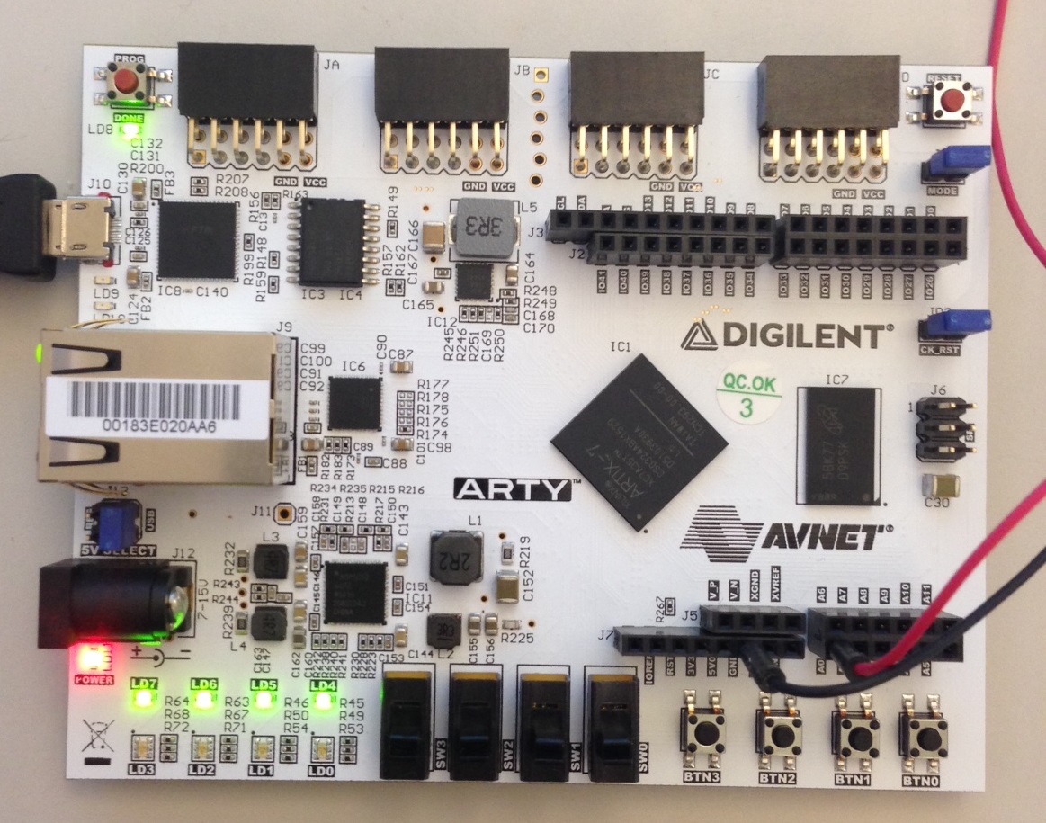
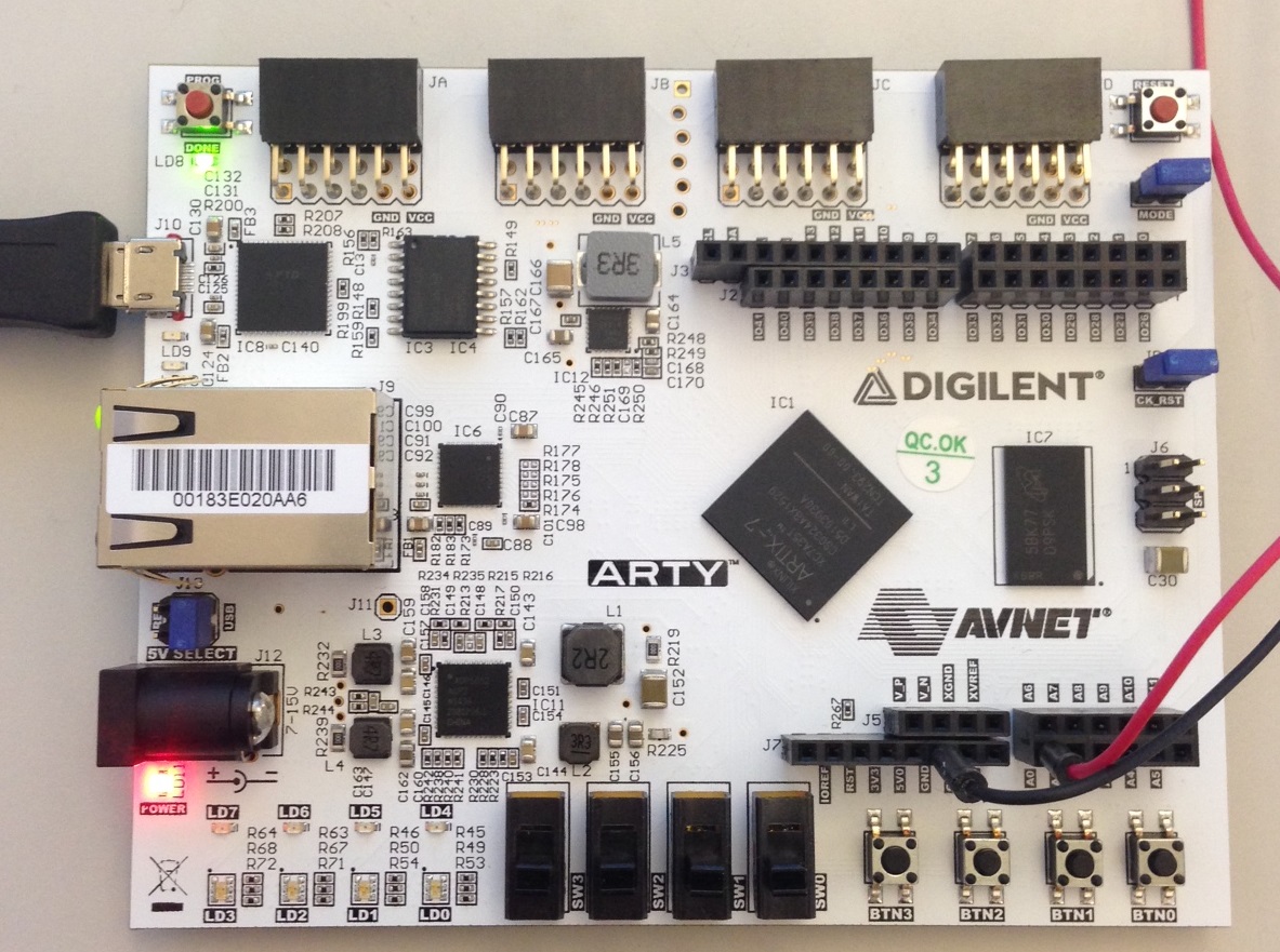
1) Applying a voltage to the XADC port
For this demo, A0-A5 are single ended analog pins while A6-A7, A8-A9, and A10-A11 are differential ports.
Important
Voltages to be measured should only be in the range of 0 to 1 Volt.
2) LEDs
The LEDs turn on from right to left then wrap around the bottom as the input voltage increases.

3) Selecting a channel
To display a different channel on the display and LEDs, change the user switches to the desired channel, as seen in the table below.
| Channel Pin/s | SW0 | SW1 | SW2 | SW3 |
|---|---|---|---|---|
| A0 | Down | Down | Down | Down |
| A1 | Up | Down | Down | Down |
| A2 | Down | Up | Down | Down |
| A3 | Up | Up | Down | Down |
| A4 | Down | Down | Up | Down |
| A5 | Up | Down | Up | Down |
| A6-A7 | Down | Up | Up | Down |
| A8-A9 | Up | Up | Up | Down |
| A10-A11 | Down | Down | Down | Up |