Add a Pmod IP to a Block Design
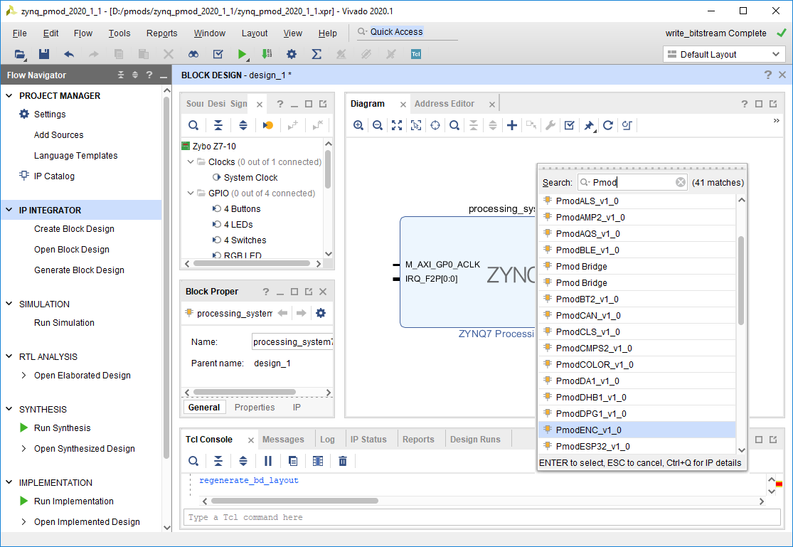
Use the Add IP ( ) button to add the IP for your Pmod to your block design.
Check the Pmod IP Design Requirements page to determine whether your Pmod is supported. Most Pmod IPs support the Pmod that they are named after, however, there are several exceptions - for example, the Pmod LED is supported by the PmodGPIO IP.
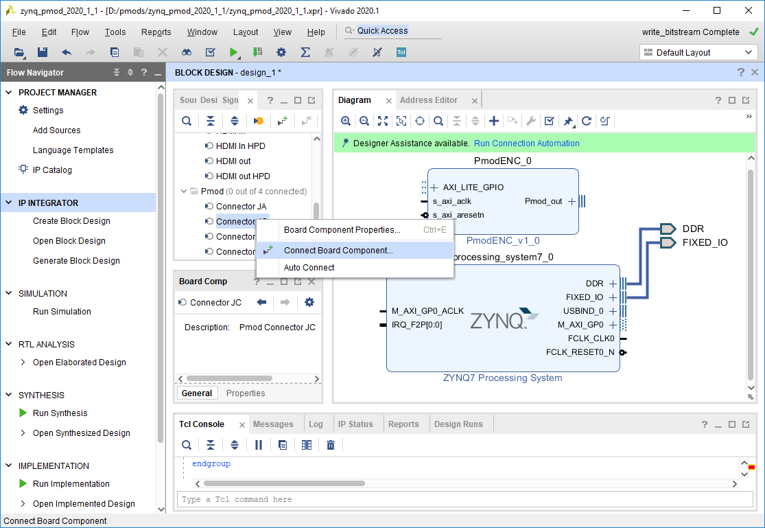
To connect your Pmod IP to a Pmod Port, navigate to the Board tab in the pane to the left of the block diagram. Digilent FPGA board files provide Pmod interfaces in this tab. Scroll down to find a Pmod connector you want to connect your Pmod to, right click on it, and select Connect Board Component.
Important: The Pmod connector you select here is the one that you must connect it to when running the design on your board.
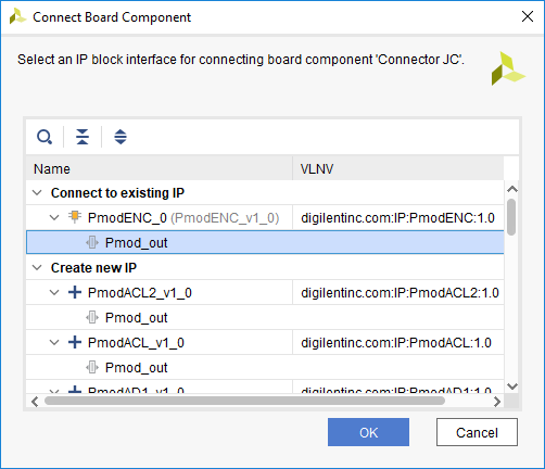
In the dialog that pops up, select your Pmod IP's Pmod_out interface under the Connect to existing IP dropdown, then click OK.
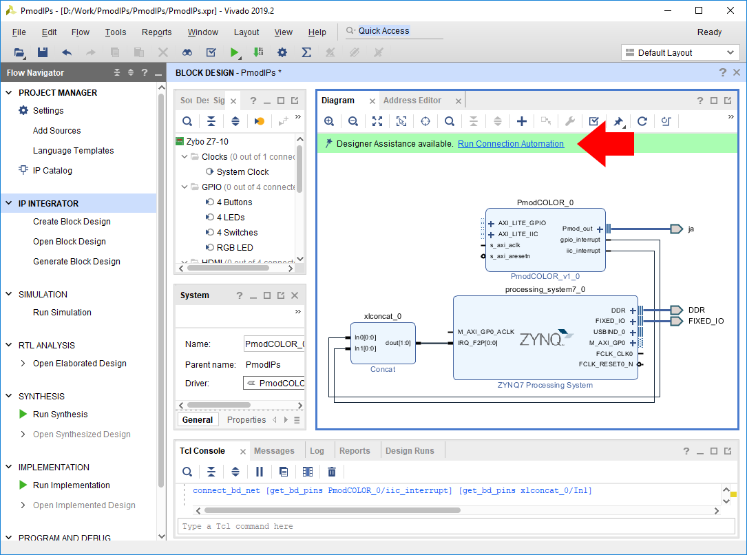
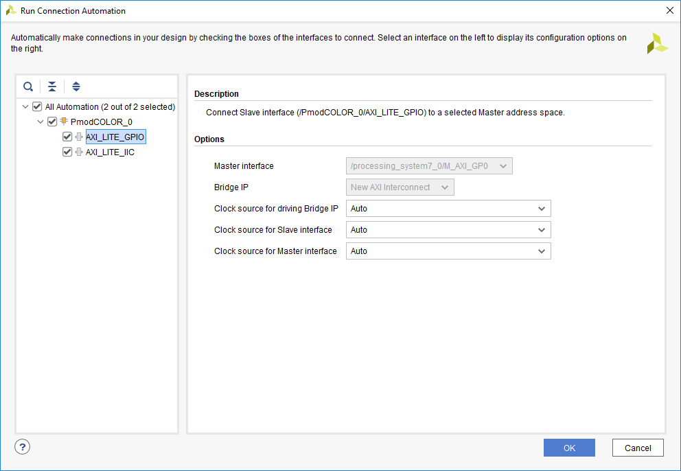
Click Run Connection Automation in the green Designer Assistance bar. This will allow you to easily connect the Pmod's AXI interface/s to your processor.
In the dialog that pops up, make that each box corresponding to your Pmod IP's AXI interfaces is checked.
Review the Clocking Requirements for Pmod IPs Table. If your Pmod IP specifies requirements for its AXI clock frequency, use the Clock source for Slave interface dropdown to select an appropriate clock. If an appropriate clock is not present in the design, you may need to return to the Add a Processor to a Block Design section of this guide.
Click OK to continue. This process will add several additional IP to the block design, including an interconnect, that can be used to route multiple AXI connections, and a processor reset system, which is used to synchronize reset signals for AXI IP.
If all ports on your IP are now connected to something (in the diagram's Default View), you are done, and can skip to the next section.
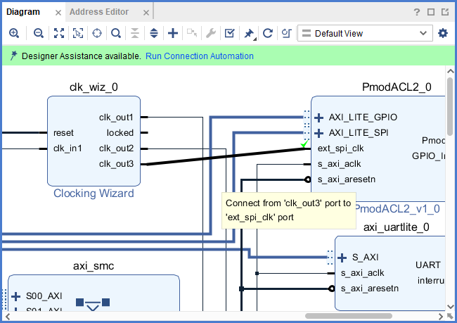
If your Pmod IP has an ext_spi_clk port, it should be connected to an additional clock of a frequency specified in the Clocking Requirements for Pmod IPs Table. Adding additional clocks to your design was discussed previously, in the Add a Processor to a Block Design section of this guide.
If your Pmod IP has one or more interrupt ports, they can be connected to your processor's interrupt system. Review the Interrupt Requirements for Pmod IPs Table to determine whether an interrupt pin is required to run the software example for your Pmod. Enabling or adding interrupt support to your processor was discussed previously, in the Add a Processor to a Block Design section of this guide. Interrupts that are not required can safely be left disconnected.
Each of these connections must be manually made by clicking and dragging from one pin to another. Pictured is a 50 MHz output clock being connected to a Pmod ACL2's external SPI clock.

