Voltage
The fundamental unit in any electrical circuit is electric charge. The goal of any electrical circuit is to move charge around in a way that performs a desired task. (For example, we can create light with an incandescent light bulb by passing electric charges through a filament rapidly enough to heat up a filament to the point that it glows.) Electric charge is carried by the electrons in atoms, so we are fundamentally concerned with moving electrons around in a way that accomplishes some goal (such as creating light in a light bulb).
Although charge is our fundamental unit, engineers are generally not directly interested in the individual charges themselves. As mentioned above, it is the motion of the charges that accomplishes our task. It is more convenient for engineers to describe the motion of charges in terms of the secondary quantities of voltage and current. In this section, we will discuss voltage.
Moving charges around typically requires an expenditure of energy. Voltage is a measure of the energy available to move a charge from one point to another in a circuit. Since voltage differences in a circuit create a force which can be used to move charges around, it is sometimes called an electromotive force, or emf.
Note: This concept is analogous to lifting a weight in a gravitational field— raising the weight requires an expenditure of energy, while lowering the weight provides energy which can be used for other purposes. Potential energy quantifies the energy available to move a mass up or down in a gravitational field, in the same way that voltage quantifies the energy available to move charges around. Because of this analogy, voltage is sometimes called electric potential.
Units of voltage are volts (V). A voltage difference of three volts is typically denoted as 3V. Small voltages are often presented in millivolts (abbreviated mV, one millivolt is equal to one thousandth of a volt). These units are used as appropriate when the Analog Discovery displays voltages.
Voltage Polarity
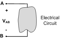
An important aspect of any voltage value is its polarity. Voltage is an energy level difference between two points, and the polarity of the voltage simply indicates which point has the higher energy level. Voltage polarities are typically indicated on circuit diagrams by “+” and “-” signs, as shown in Fig. 1. The blob in Fig. 1 indicates an electrical circuit or circuit element. Two terminals of the circuit are accessible and are labeled as A and B in Fig. 1. The voltage between these two terminals is denoted as VAB. The + sign near terminal A and the “-” sign near terminal B indicate that the voltage at terminal A is higher than the voltage at terminal B.

The above interpretation of polarity is only correct if the voltage VAB is a positive number. If VAB is a negative number, the voltage at terminal A is higher than the voltage at terminal B by a negative amount—this is equivalent to saying that the voltage at terminal A is lower than the voltage at terminal B.
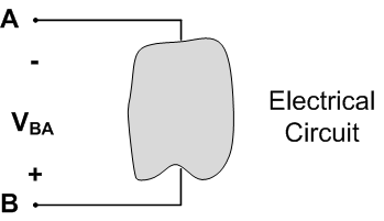
Note: The voltage polarity indicated on circuit schematics only provides a sign convention by which to interpret voltages. It indicates the polarity associated with a positive voltage. If the voltage is negative, the polarity is simply reversed. Therefore, if we re-define the polarity of the voltage difference of Fig. 1 as shown in Fig. 2, the voltage VBA in Fig. 2 is simply the negative of the voltage VAB in Fig. 1, or VBA = -VAB.

Ground
Voltage is always a difference in energy between two points. However, it is often convenient to specify a reference voltage level of “zero” volts and then express voltages at other points in a circuit relative to that voltage. When we do this, it looks as if we are talking about voltage at a single point, but we are actually expressing the voltage at that point relative to some (rather arbitrary) reference voltage which is taken to be zero. This reference voltage is called ground.
The above interpretation of polarity is only correct if the voltage VAB is a positive number. If VAB is a negative number, the voltage at terminal A is higher than the voltage at terminal B by a negative amount—this is equivalent to saying that the voltage at terminal A is lower than the voltage at terminal B.
Note: The overall idea is similar to that used when we define altitudes in geography. Altitudes are, by common agreement, specified relative to sea level. “Sea level” provides a rather arbitrary definition of where “zero” altitude is. Altitudes can be either positive (above sea level) or negative (below sea level), just as voltages can be either positive or negative relative to ground.
Ground, in electrical circuit schematics, is denoted by one of the symbols shown in Fig. 3. Although all three symbols define a zero volt level for any other voltages on the schematic, they do not mean the same thing. Earth ground, Fig. 3(a), uses the convention of the earth's potential energy being zero volts— this definition of ground is the basis of most safety regulations. Earth ground on a circuit schematic implies that there is some physical connection between the circuit and the earth. Signal ground, Fig. 3(b), and chassis ground, Fig. 3©, do not necessarily imply that there is a physical connection to the earth— these symbols are appropriate, for example, for circuits on a satellite orbiting the earth.
For now, we will use as our only ground definition “signal ground”. On circuit schematics, signal ground is indicated by the symbol shown in Fig. 3(b). We will discuss more details about the differences among various grounds in a different project.
Voltage Measurement
Voltage differences are usually measured with a voltmeter. A voltmeter will have two terminals, or leads, which are connected to the two points in our circuit across where we want to measure voltage. For example, suppose that we want to measure the voltage across circuit 2 (V2) shown in Fig. 4(a). We simply connect the terminals of the voltmeter to the terminals of circuit 2 in order to measure the voltage across circuit 2, as shown in Fig. 4(b).
Generally, voltmeters are implemented as one function of a digital multimeter, or DMM. DMMs are one of the most common pieces of electrical test equipment— most DMMs will measure at least voltage, current, and resistance. Since DMMs have multiple functions, there are multiple “settings” on the meter (selected by push buttons or turning a dial), and several ways in which the terminals can be connected to the DMM (by inserting the leads of the DMM into different ports on the meter). When using a DMM to measure constant voltages, the appropriate setting is indicated by the letter “V” with a bar over it, and the terminals are plugged into ports labeled as “V/ Ω” and “COM” (for common). The “V/ Ω” terminal is connected to the assumed positive voltage terminal in your circuit, and the “COM” terminal is connected to the assumed negative voltage terminal in your circuit. It is customary to use a red lead for the “V/Ω” terminal and a black lead for the “COM” terminal.
Important Points
- Voltage is an energy level difference between two points. This energy difference can be used to move charges around. The units of voltage are volts, abbreviated V.
- To specify a voltage, you have to include not only a magnitude (the number of volts) but also a polarity. The polarity of a voltage is indicated by “+ ” and “-” signs on a circuit diagram. The “+” sign is at the point where the voltage is assumed to be higher, while the “- ” sign is at the point which is assumed to have the lower voltage. This polarity does not necessarily correspond to the actual voltage polarity, but it shows the direction associated with a positive voltage.
- The magnitude of a voltage can be either positive or negative. If the voltage magnitude is positive, the voltage has the same polarity as shown on the diagram. If the voltage magnitude is negative, the voltage polarity is the opposite to that shown on the diagram. Switching the polarity on the diagram simply changes the sign on the voltage and vice-versa.
- Voltage is measured using a voltmeter. In order to measure a voltage in a circuit, simply connect the voltmeter terminals at the two points across which the voltage difference is desired.
Test Your Knowledge
- For the circuit elements below, the voltage difference and polarity is provided. State which terminal is at the higher voltage, and what the voltage difference is.
- Ground and a voltage difference are shown for the circuit elements below. Determine the voltage of node 'a' relative to ground.
Answers
1.
- Node a is 3V higher than node b.
- Node a is 3V higher than node b. (The voltage is negative, which switches the assigned polarity.)
- Node b is 3V higher than node a.
- Node b is 3V higher than node b. (The negative sign on the voltage reverses the indicated polarity.
2.
- Node a voltage is 2V below ground.
- Node a voltage is 3V below ground. (It is negative 3V above ground, the negative sign inverts the polarity.)
- Node a voltage is 3V below ground.
- Node a voltage is 3V below ground. (It is negative 3V above ground, so it is positive 3V below ground.)


