Practical Resistors
Introduction
Resistors are the most frequently used components in electrical circuits. Since they are so common, they are available in a wide variety of styles and manufacturing techniques. In this section, we won't attempt to provide a comprehensive discussion of all available resistors. Instead, we will provide a simple guide to the types of resistors generally used for building prototype circuits on breadboards.
Resistors are manufactured in a variety of ways. Most commonly available commercial resistors are carbon composition or wire-wound; however, resistors on integrated circuits are generally made of semiconductor materials.
Resistors can have either a fixed or variable resistance. Identification and use of these two types of resistors is (at least superficially) fairly different, so we will discuss them separately in the subsections below.
Variable Resistors
Variable resistors, sometimes called rheostats or potentiometers, have resistance which may be varied by a mechanical control (usually a knob or a screw) or an electronic one. Potentiometers have three pins while rheostats have two pins. Potentiometers are more common since they can be used as rheostats1). The Digilent analog parts kit contains a variety of potentiometers. A potentiometer from the parts kit is shown in Fig. 1.
The pins of a typical potentiometer are shown in Fig. 2. The control sets the resistance between terminals 1 & 2 (R13) and between terminals 2 & 3 (R23). In an ideal potentiometer R13 + R23 is a constant. For the potentiometers in the Digilent analog parts kit, the total resistance R13 + R23 is encoded in exponential notation on the top of the potentiometer as three numbers. The first two numbers are the mantissa of the number; the third number is the exponent. For the potentiometer shown in Fig. 1, the encoded number is 502. This corresponds to a resistance of 50×102, or 5000Ω. This means that both R13 and R23 can be adjusted to between 0Ω and 5000 Ω.
Fixed Resistors
Fixed resistors provide a single specified resistance value and have two terminals. The circuit symbol for a fixed resistor is shown in Fig. 3. The Digilent analog parts kit provides two types of fixed resistors: a large power resistor and a variety of smaller, low power resistors. Examples of both types of resistors are shown in Fig. 4.
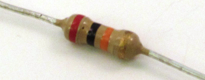
Resistors that are physically large enough will usually have their resistance value printed directly on them, as in the resistor of Fig. 4(b). Smaller resistors, like those shown in Fig. 4(a), generally use a color code to identify their resistance value. The color code consists of a series of three to six colored bands. The color coding scheme is provided in Fig. 5. All resistors in the Digilent analog parts kit have four bands—for these resistors, the first three bands provide a nominal resistance value2) in exponential notation. Like the potentiometer, these colors correspond to a number in exponential notation; the first two colors correspond to numbers which give the mantissa of the number, and the third band provides the exponent. The fourth color band provides a tolerance between the actual and expected resistance. An example of calculating a nominal resistance from a color code is provided below.
Example
A resistor has the following color bands below. Determine the resistance value and tolerance.
- First band: Red
- Second band: Black
- Exponent: Orange
- Tolerance: Gold
Resistance = (20+0)x103 ± 5% = 20kΩ ± 1k Ω
Important Point
Resistors can be fixed or variable. The most common resistors in the Digilent analog parts kit are small fixed resistors. The resistance values for these resistors are encoded on the resistors in a series of colored bands. The color codes are provided in Fig. 5 above. You should make an effort to understand how to determine a resistance value from the color code on the resistor.


