Quick Start Guide
What's in the Box?
- Electronics Explorer Board
- Starter Parts Kit
- Contains resistors capacitors, diodes, transistors, an LED, wires, and other components.
- The main page has a detailed list of what's included in the Starter Parts Kit.
- Micro-B USB Cable
- Power Supply
- Adapter for European outlets included
- Input: 100-240V, Output: 12V/2A
Setting up the Board
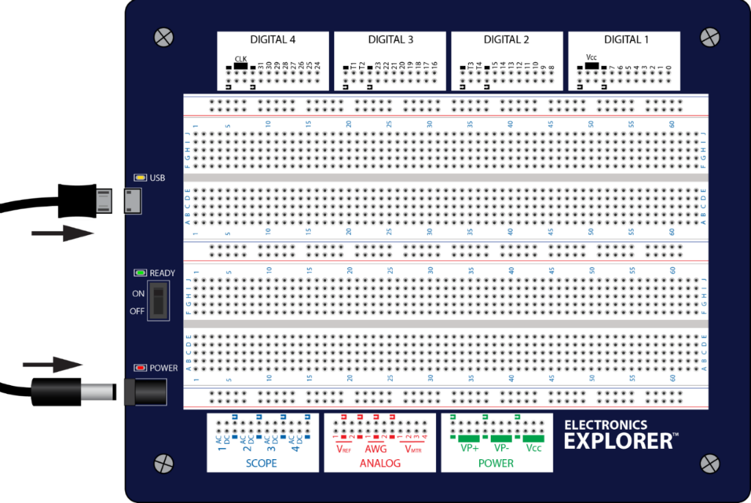
- Connect the EE Board to your PC with the USB cable. A successful connection is indicated by a yellow/orange LED.
- Connect the board's external power supply. A successful connection is indicated by a red LED.
- Flip the “Ready” switch on the board to the “ON” position.
- Note: All three of these steps must be followed for the board to be recognized in WaveForms.
Selecting the Board in WaveForms
- If you have not already, you can download the WaveForms Software for free from Digilent's website.
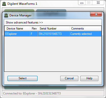
- When you first open WaveForms the Device Manager window should automatically appear. Click your “EExplorer” and click the “Select” button. Your EE Board is now connected to WaveForms and ready for use. The green LED next to the “Ready” switch indicates if the EE Board is connected to WaveForms.
Using the Board
 This portion of the board provides the EE Board's Power Supplies. In WaveForms these power supplies are accessed with the
  tool. This “Voltage” tool offers a voltmeter as well as power supplies. When you open this tool, you will notice that the Power Supplies available (VP+, VP-, Vcc) correspond to the labels on the board. The rows book-ended with the
  symbol denote ground pins. This applies for the other sections of the board as well.
 This portion of the EE Board provides access to useful analog design tools including an Arbitrary Waveform Generator (AWG), a Voltmeter (VMTR), and Reference Voltages (VREF). The Voltmeter and Reference Voltages are accessed in the same Voltage tool previously mentioned. The AWG is accessed in WaveForms through the
  tool. Note, the numbers on the board refer to different channels in WaveForms.
 This portion of the EE Board provides access to the WaveForms Oscilloscope tool. This tool can be accessed by clicking the
  button in the WaveForms main window. Again, the numbers refer to separate channels within the WaveForms Oscilloscope. That being said, 4 separate signals can be scoped at the same time. Also, as one might expect, the rows in each channel labeled AC and DC are for measuring AC and DC signals, respectively.
 Digital 1-Digital 4 provide access to all the pins necessary for digital design. The numbered rows, 0-31, refer to the digital input/outputs DIO 0-31 in WaveForms. The following WaveForms instruments have access to these I/O pins:
The rows labeled as T1, T2, T3, and T4 refer to “triggers”.
For more information on how to specifically use the board and WaveForms Instruments, check out the Introductory Projects.


