Building a DIY Speaker
In this guide, the main components and the working principles of a loudspeaker will be presented. You can follow along to build your own speaker.
Inventory
For Measuring
- a PC with WaveForms installed
- a small speaker - optional, for measurements only
Tools
- scissors
- wire cutter
- wire stripper
- sandpaper
- soldering iron
- marker
- tape measure
For the Speaker
- thin, insulated copper wire
- stationery tape
- some thicker wire
- a larger plastic cap
- two pieces of small neodymium magnets
For the Amplifier
- 50 kΩ potentiometer
- 10 kΩ resistor (3x)
- OP37 operational amplifier
- 1N914 diode (2x)
- 2N3904 NPN transistor
- 2N3906 PNP transistor
- audio connector
- breadboard
Note: All the above components can be found in the Analog Parts Kit.
How a Loudspeaker Works
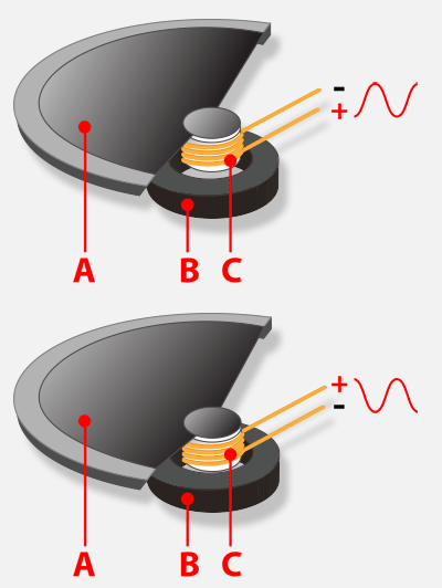
A loudspeaker is a device that translates electrical signals to sound. A basic loudspeaker (or speaker) has four parts: the magnet (B), the coil (C), the diaphragm (A) and the chassis. The diaphragm is fastened to the chassis, in a way that its center can vibrate. The coil is glued to the center of the diaphragm. The magnet is placed beneath the coil and is fixed to the chassis.
When a current flows through the coil, it induces a magnetic field around it so that the fixed magnet attracts or repels the coil, according to the polarity of this field. As the diaphragm is glued to the coil, it moves along. The air in front of the diaphragm is “pushed”, or “pulled”, by the moving diaphragm, becoming denser in some places and thinner in other places. This creates a longitudinal wave in the air, which is the sound itself.
 By Christophe Dang Ngoc Chan (cdang) - Own work, CC BY-SA 3.0, https://commons.wikimedia.org/w/index.php?curid=1386746
What is Impedance?
Impedance is the opposition of a device to the flow of alternating current. The impedance of a device is a complex quantity: $Z=R+jX$, where $Z$ is the impedance, $R$ is the resistance of the device and $X$ is a quantity called reactance. The reactance of the device is frequency and device type dependent as $X_L=2{\pi}fL$ and $X_C=\frac{1}{2{\pi}fC}$ are the formulae for inductive and capacitive reactance. If we take $Q=\frac{X}{R}$ (also called quality factor), we will know the ratio of the energy stored in the device to the energy dissipated by it.
While it is very important, performing calculations with complex quantities, such as the impedance, can become problematic in some circuits. This is where the impedance analyzer comes into play.
Using the Impedance Analyzer
The first step in building your own speaker is to analyze the most significant properties of an existing speaker. You can use the one found in the Analog Parts Kit.
Use the Impedance Analyzer to measure the magnitude of the impedance of the speaker between 20 Hz and 20 KHz, as these are the lower and the upper limits of human hearing. In this case, the magnitude of the impedance is almost constant, around 8 Ω, for a while, then starts to increase.
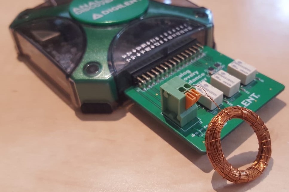
Now cut a piece of copper wire, around 1 m to 1.5 m, and wind it around the marker to make a coil. Use sandpaper to clean both ends of the wire.
Measure the magnitude of the impedance of this small coil. In this case, 1.5m of wire was used, and the resulting magnitude is around 0.9 Ω. Use the following formula to calculate the length of the wire needed for the speaker: $l_{wire}=l_{small-wire}*\frac{|Z|_{speaker}}{|Z|_{small-wire}}=1.5m*\frac{8Ω}{0.9Ω}$.
Calculate how much wire you need, then use the tape measure and cut it. Wind the wire around the marker. Use the sandpaper to clean the ends, then measure the magnitude of its impedance. You should get a value close to the speaker's magnitude of impedance. In this case, the value starts a bit below 8 Ω and starts to increase earlier, but that increase will only affect high pitch sounds.
If you are satisfied with the results, solder two thicker wires to the ends of your coil.
Building the Speaker
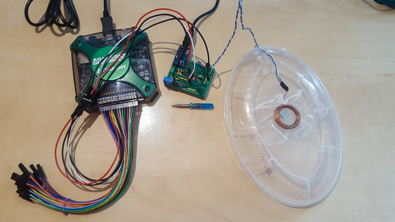
Place the two magnets above and below the plastic cap and let them attract one another, so that they remain fixed to the cap.
Put the coil between two pieces of stationery tape, then fix the two ends of the tape on the sides of the cap, so the magnets are below the middle of the coil.
You can use another piece of stationery tape to fix the cables coming from the coil.
Building the Amplifier
Currently, if you connect music to the speaker, you will hear nearly nothing, as the current flowing through your speaker isn't high enough. For your loudspeaker to be loud, you will need to build an amplifier.
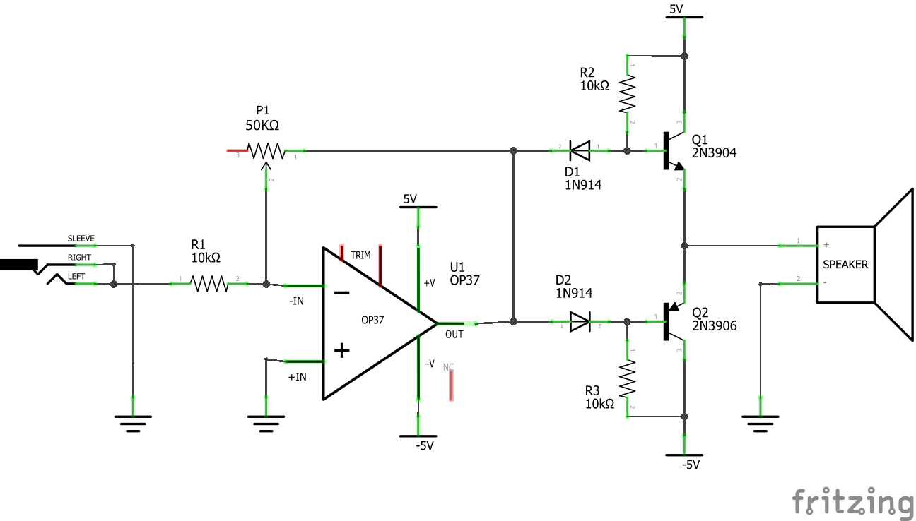
On a breadboard, build an inverting amplifier, using the OP37 operational amplifier, a 10 kΩ resistor, and a 50 kΩ potentiometer. This amplifier stage will increase the amplitude of the signal, but the output current will remain limited to a few milliamps. To increase the current, build a class AB power amplifier using two diodes, two resistors, and two BJTs, an NPN and a PNP.
You can use the V+ and V- pins of the Analog Discovery 2 as a differential power supply. You can use an audio connector on the input.
Testing
Connect your PC or phone to the audio input and play some music. Use the potentiometer to turn up the volume. Apply “sound effects” by slightly moving the magnets towards one side of the coil.
If you would like to play music on your DIY speaker louder, you can experiment with setting a higher gain for your amplifier, but pay attention to the power rating of your power supply: if the Analog Discovery 2 can't supply the necessary current, the voltage will drop.
Optionally, you can test your speaker with a power amplifier, if you have one. You may reach louder volumes and even better sound quality in this case.
The coil of the speaker might get hot if too much current flows through it!
Next Steps
For more guides on how to use your Test and Measurement Device, return to the device's Resource Center, linked from the Test and Measurement page of this wiki.
For more information on WaveForms, visit the WaveForms Reference Manual.
For technical support, please visit the Test and Measurement section of the Digilent Forum.

