Table of Contents
Eclypse Z7 Digital Low Pass Filter Demo

Overview
The demo demonstrates the implementation of a basic signal processing application on the Eclypse platform (Eclypse Z7 + Zmod ADC + Zmod DAC).
Description
The simplified block diagram of the system implemented for this demo is shown in Figure 1. The hardware elements required are: an Eclypse Z7 board, a Zmod ADC 1410 module, a Zmod DAC 1411 module and an Analog Discovery 2 (AD2). The Network Analyzer running on AD2 will be used to generate a sinusoidal signal (perturbation) on the AWG1 channel.
The following connections have been made in order to obtain the desired results:
- Analog Discovery 2 AWG1 to AD2 SCOPE C1
- Zmod ADC1410 CH1 to Eclypse Z7 SYZYGY Port A
- Zmod DAC1411 CH1 to Eclypse Z7 SYZYGY Port B
- Zmod DAC1411 CH1 to Analog Discovery 2 SCOPE C2
Only the programmable logic (PL) of the Zynq is used for this project. The signal processing chain consists of: - the Zmod ADC 1410 Low Level Controller - initializes the Zmod ADC 1410 hardware and synchronizes the incoming data in the user clock domain, - A digital low pass filter – implemented using Xilinx FIR compiler IP - a Zmod DAC 1411 Low Level Controller that initializes the Zmod DAC 1411 hardware and formats the output data according to the AD9717 DAC requirements. The Network Analyzer instrument will use the AWG and Scope Channels of the AD2 to plot the frequency response of the filter (Figure 2).
Filter Design
The Low Pass Filter was designed using MATLAB Filter Designer tool. The input specifications are presented in Figure 3.
Features Used
| Not Used | Used | |
|---|---|---|
| 4 slide switches | X | |
| 5 LEDs | X | |
| 2 RGB LEDs (1*) | X | |
| 6 push buttons | X | |
| USB-UART Bridge | X | |
| Micro SD card connector | X | |
| HDMI Sink | X | |
| HDMI Source | X | |
| Pcam camera connector | X | |
| Audio codec w/ three 3.5mm jacks | X | |
| User EEPROM | X | |
| 10/100/1000 Ethernet PHY | X | |
| 1GB 1066MHz DDR3 Memory | X | |
| Serial Flash | X | |
| 6 Pmod ports (5*) | X | |
| Pmod for differential analog signals | X | |
| USB HID Host | X |
Prerequisites
Skills
- Basic familiarity with Vivado
- This experience can be found by walking through our “Getting Started with Vivado” guide
Hardware
- Zybo Z7 Zynq board
- Micro-USB cable
- Headphones or Speakers
- Audio Input device (Aux-In, Guitar, etc.)
Software
- Vivado Design Suite 2016.X
- Newer/older versions can be used, but the procedure may vary slightly
- Digilent Board Support Files for Vivado
- Follow the Vivado Board Files for Digilent 7-Series FPGA Boards guide on how to install Board Support Files for Vivado.
Downloads
Zybo Z7-10 DMA Audio Project Repository – ZIP Archive GIT Repo
Zybo Z7-20 DMA Audio Project Repository – ZIP Archive GIT Repo
Download and Launch the Zybo Z7 DMA Audio Demo
1) Follow the Using Digilent Github Demo Projects Tutorial. Since this is a Vivado SDK Project, you can either directly launch SDK and import the hardware handoff, or you can generate a bitstream in Vivado before launching SDK. Select the hardware handoff options in the tutorial if you don't want to modify the project block design later. Return to this guide when prompted to check for additional hardware requirements and setup.
2) In order to use the demo, you will need to plug in your microphone (MIC) or aux input into the respective jack on your Zybo. Plug your speakers/headphones into the headphone (HPH) out jack.

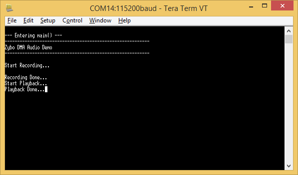
3) Turn on your board and open a serial terminal (such as TeraTerm) on your computer to receive status messages. Setup the serial port to connect to the appropriate port for your board, with a baud rate of 115200. Then return to the Github Project Tutorial to finish programming and running the demo.
Tip
You can connect your serial terminal to your board before the board is programmed, this will make sure that you don't miss any startup messages. If the demo is already running, you can restart the demo in SDK to make sure you get these messages.

Using the Zybo Z7 DMA Audio Demo
1. Controls
Audio playback and recording are controlled by push buttons as below.
| Button | Function |
|---|---|
| BTN0 | no effect |
| BTN1 | record from mic in |
| BTN2 | play on hph out |
| BTN3 | record from line in |
2. Recording from an input
To record from the microphone input, press BTN1. To record from the line input, press BTN3. Once the recording is activated, the message “Start Recording…” will be sent over UART and the demo will record 5 seconds of audio. If any buttons are pressed during the recording, the message “Still Recording…” will be sent over UART.
3. Playing to an output
To play to the headphone output, press BTN2. Once the playback is activated, the message “Start Playback…” will be sent over UART and the demo will play 5 seconds of audio. If any buttons are pressed during the playback, the message “Still Playing…” will be sent over UART.