Table of Contents
Pmod TPH2 Reference Manual
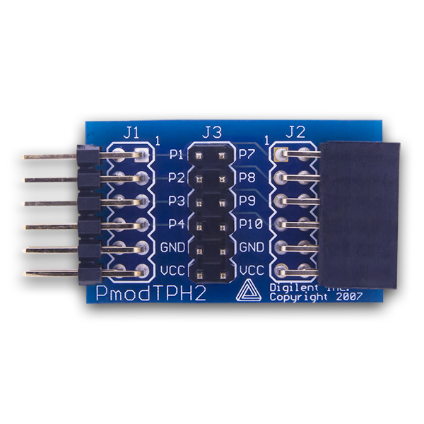
The Pmod TPH2 (Revision A) is a 12 point test header, giving users easy access to any signals passing through the Pmod.

Download This Reference Manual
Features
- 12 external test point headers
- Easily access and test signals passing through
- 12-pin Pmod connector with GPIO interface
Functional Description
Offering 12 isolated pass through connectors, this module is able to easily able to be placed between two pieces of hardware allowing the user to observe and debug their circuit.
Interfacing with the Pmod
Attach your multimeter or oscilliscope (such as the Analog Discovery) to the vertical test point headers and measure away!
Pinout Table
| Header J1 | ||||||
|---|---|---|---|---|---|---|
| Pin | Signal | Description | Pin | Signal | Description | |
| 1 | 1 | Pass through #1 | 7 | 7 | Pass through #7 | |
| 2 | 2 | Pass through #2 | 8 | 8 | Pass through #8 | |
| 3 | 3 | Pass through #3 | 9 | 9 | Pass through #9 | |
| 4 | 4 | Pass through #4 | 10 | 10 | Pass through #10 | |
| 5 | 5 | Pass through #5 | 11 | 11 | Pass through #11 | |
| 6 | 6 | Pass through #6 | 12 | 12 | Pass through #12 | |
Any external power applied to the Pmod TPH2 must be able to be handled by your two pieces of hardware on either side of the Pmod.
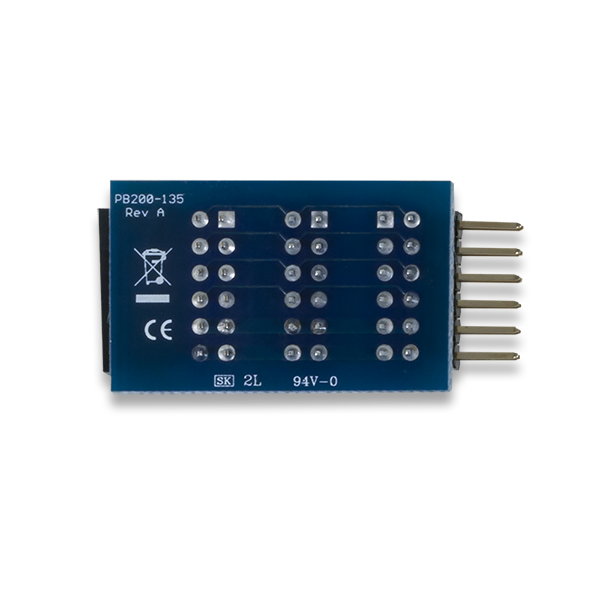
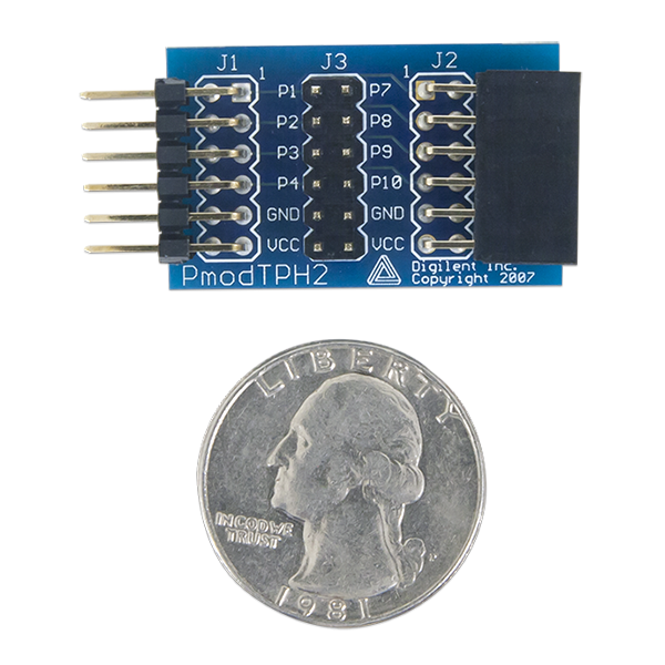
Physical Dimenions
The pins on the pin header are spaced 100 mil apart. The PCB is 1.3 inches long on the sides parallel to the pins on the pin header and 0.8 inches long on the sides perpendicular to the pin header.
Additional Information
The schematics of the Pmod TPH2 are available here.
As a straight pass through connector, no example code is available for this module.
If you have any questions or comments about the Pmod TPH2, feel free to post them under the appropriate section (“Add-on Boards”) of the Digilent Forum.