Table of Contents
Pmod SWT Reference Manual
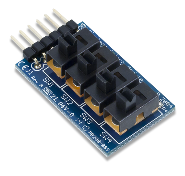
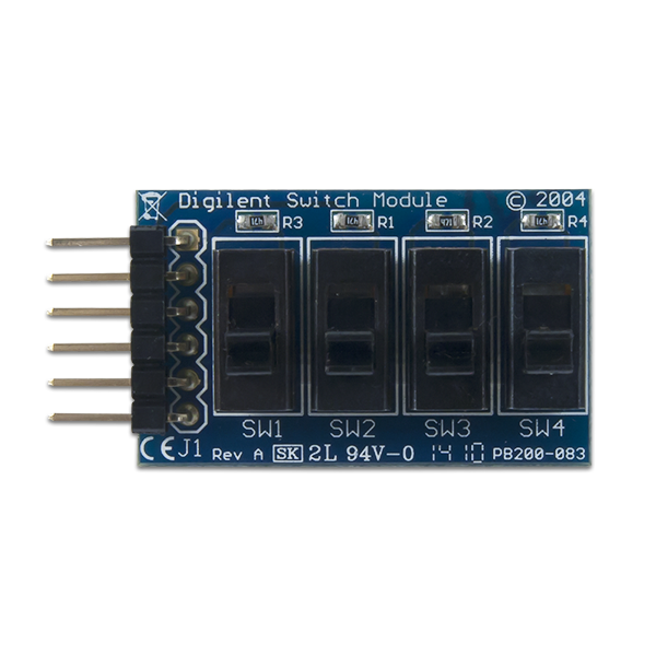
The Digilent Pmod SWT (Revision A) offers 4 user switches that effectively work as on and off switches.

Download This Reference Manual
Features
- 4 slide switches
- Add user input to host board or project
- Static binary logic input
- 6-pin Pmod port with GPIO interface
Functional Description
The Pmod SWT utilizes four slide switches that users can use as a set of on and off switches or as a set of static binary inputs.
Interfacing with the Pmod
The Pmod communicates with the host board via the GPIO protocol. When a switch is turned to the “on” position, it's respective pin will be at the logic level high voltage and when a switch is off, the pin will be a logic level low voltage.
Pinout Description Table
| Pin | Signal | Description |
|---|---|---|
| 1 | SWT1 | Switch 1 input |
| 2 | SWT2 | Switch 2 input |
| 3 | SWT3 | Switch 3 input |
| 4 | SWT4 | Switch 4 input |
| 5 | GND | Power Supply Ground |
| 6 | VCC | Positive Power Supply |
There are no integrated circuits on the Pmod SWT, so any voltage range that is usable with your system board can be used on the Pmod SWT.
Physical Dimensions
The pins on the pin header are spaced 100 mil apart. The PCB is 1.3 inches long on the sides parallel to the pins on the pin header and 0.8 inches long on the sides perpendicular to the pin header.
Additional Information
The schematics of the Pmod SWT are available here.
Example code demonstrating how to get information from the Pmod SWT can be found here.
If you have any questions or comments about the Pmod SWT, feel free to post them under the appropriate section (“Add-on Boards”) of the Digilent Forum.