Table of Contents
Pmod ESP32 Reference Manual
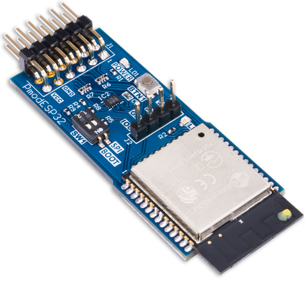
The Digilent Pmod ESP32 features a radio with support for 802.11 b/g/n Wifi and dual-mode Bluetooth. This module is perfect for connecting your FPGA or microcontroller projects to your home network, the internet, or any bluetooth hardware. The Pmod ESP32 contains a Tensilica Xtensa microprocessor, which can be operated in slave mode with AT commands over a UART interface. Additionally, the Pmod ESP32 can be operated in standalone mode and run custom applications. In slave mode, the module can be configured as an access point to host a Wifi network, or a station to connect to an existing network. Slave mode functionality over UART is made easy through the use of a well documented AT command set. An additional UART port is provided on the top of the module for system debugging and firmware flashing. Standalone mode gives the user access to the full API and SDK provided by Espressif for operation through the use of the Xtensa tool-chain. The Pmod ESP32 is a great and cost-effective way to add WiFi and Bluetooth to any project.
Features
- Full 802.11 b/g/n WiFi stack with support for TCP, UDP, and SSL connections
- Connect to WiFi networks or broadcast your own as a server or a client
- Bluetooth v4.2 BR/EDR and BLE compatibility
- One UART port for system debugging and application flashing
- One programmable on-board LED
- Two customizable GPIO pins
- 20.5 dBm output power at the antenna
- User button for resetting the processor after a mode switch
- User switch for toggling between UART and SPI communication
- Low power sleep mode for battery powered applications
- 12-pin Pmod connector with SPI and UART interfaces
- Follows Digilent Pmod Interface Specification 1.2.0
Specifications
Pinout Table Diagram
| Pin | Signal | Description |
|---|---|---|
| 1 | RTS / SS | UART Request to Send / SPI Slave Select |
| 2 | RXD / MOSI | UART Receive Data / SPI Master Out Slave In |
| 3 | TXD / MISO | UART Transmit Data / SPI Master In Slave Out |
| 4 | CTS / SCK | UART Clear to Send / SPI Serial Clock |
| 5 | GND | Power Supply Ground |
| 6 | VCC | Power Supply (3.3V) |
| 7 | INT | Configurable GPIO / IO2 |
| 8 | EN | Reset Enable |
| 9 | SELECT | UART or SPI Mode Select |
| 10 | GPIO | Configurable GPIO / IO32 |
| 11 | GND | Power Supply Ground |
| 12 | VCC | Power Supply (3.3V) |
Power Specifications
| Parameter | Min | Typical | Max | Units |
|---|---|---|---|---|
| VDD | 2.7 | 3.3 | 3.6 | Volts |
UART/SPI Clock Specifications
| Parameter | Min | Typical | Max | Units |
|---|---|---|---|---|
| SPI Serial Clock Frequency | - | 2 | 8.8 | MHz |
| UART Serial Clock Frequency | 80 | 115,200 | 5,000,000 | Baud |
Radio Specifications
| Parameter | Max | Units |
|---|---|---|
| 802.11 Max Data Rate | 150 | Mbps |
| Bluetooth HCI Max Data Rate | 4 | Mbps |
Note: Actual radio throughput is dependent on a number of factors including antenna type, operating environment, line of sight, and electromagnetic interference.
Physical Dimensions
- PCB Length: 2.00 in. (5.08 cm)
- PCB Width: 0.80 in. (2.03 cm)
Note: Dimensions do not include the length of the Pmod header pins. The ESP32 antenna overhangs the PCB by 1/4“.
Functional Description
The Pmod ESP32 integrates WiFi and Bluetooth 4.2 solutions on a single chip along with dual high performance cores and several peripherals. The ESP32 possesses the ability to connect to an existing WiFi network or broadcast its own as an access point.
The Pmod ESP32 has the ability to operate in slave mode using the UART interface on the top row of pins. In slave mode, the device responds to a specific set of AT commands. More information about the AT command firmware can be found here: ESP 32 AT Source. The device comes pre-configured with the AT command firmware installed. In slave mode, the SPI peripheral and the GPIOs on the bottom row are unused.
The Pmod also has the ability to operate in stand alone mode. In stand alone mode, the user can write custom applications for the ESP 32. Custom applications can interface with the otherwise unused SPI interface and program the two GPIOs in the bottom row of pins. To send the new application to the ESP32, the user can modify the switches and use the UART that is connected to the J2 header to both flash and monitor the device.
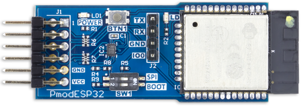
Switches
The Pmod ESP32 has two switches. SW1.1 (labeled “SPI”) controls whether the top row of the Pmod is configured as a SPI interface or UART interface. When SW1.1 is in the ON position, the top row of the Pmod is set as a SPI interface. Alternatively, when SW1.1 is set in the OFF position, the top row of the Pmod is set as a UART interface.
SW1.2 (labeled “BOOT”) controls whether the ESP32 boots into an application stored in memory or, on power-up, waits to be flashed with a new application. When the ESP32 is powered on, if SW1.2 is in the ON position, the ESP32 will enter a mode where it waits to be flashed with a new application. If SW1.2 is in the OFF position, the ESP32 will boot and begin to run whatever application it has stored in its memory.
The behavior of SW1.1 can be controlled by a host board by using the “Select” pin (pin 9 of Pmod header J1). Driving the Select pin high will cause the top row of the Pmod connector to have SPI functionality, regardless of the value of SW1.1. Similarly, driving the Select pin low will cause the top row of the Pmod connector to have UART functionality, regardless of the value of SW1.1.
Pmod ESP32 Switch Behaviors
| Switch | Value | Behavior |
|---|---|---|
| SW1.1 (SPI) | OFF | UART interface is present on pins 1 - 4 of Pmod header J1 |
| SW1.1 (SPI) | ON | SPI interface is present on pins 1 - 4 of Pmod header J1 |
| SW1.2 (BOOT) | OFF | Upon boot, the ESP32 will load the application that is currently in memory |
| SW1.2 (BOOT) | ON | Upon boot, the ESP32 will not load any application and will wait for a new application to be programmed |
Reset Button
After flashing the device with a new application, or when switching between boot modes specified by SW1.2, it is necessary to reset the ESP32. A simple press of BTN1 will cause the ESP32 to reset, regardless of the state of the Enable pin, described below.
The behavior of BTN1 can be controlled by a host board by using the “Enable” pin (pin 8 of Pmod header J1). Driving the Enable pin low will disable the ESP32. When Enable is driven high again, the ESP32 will reset and boot into the selected mode of operation.
On-board LED
The Pmod ESP32 contains an on-board LED that can be directly programmed by the user. The LED (LD0) is connected to IO12 on the ESP32. When using the AT firmware, LD0 cannot be directly controlled by the user. However, LD0 can be programmed by writing custom applications for, and flashing, the ESP32.
AT Command (Slave) Mode
The Pmod ESP32 is delivered to users in slave mode. In slave mode, the top row of pins are mapped to their UART functionality. It is important that switches SW1.1 and SW1.2 are both in the off position when power is applied to the device. Once power has been applied, the value of SW1.2 is arbitrary. However, SW1.1 must remain in the off position during the duration of operation in slave mode.
In slave mode, commands of a specific format (referred to as AT commands hereafter) are passed to the Pmod via the UART interface on the top row of pins. The UART interface on the Pmod is initially set to function at 115200 baud with 8 data bits, 1 stop bit, and no parity or hardware flow control. The settings of the UART interface can be modified by using specific AT commands later.
AT commands must always be followed by a carriage return and newline character, in that order. For example, the AT command “AT” would be typed into the serial terminal as “AT<CR><LF>”, where CR stands for carriage return and LF stands for line feed or newline. If the carriage return or line feed are not included at the end of the command, the Pmod will not respond to the command. Additionally, AT commands may be sent to the Pmod in either upper case or lower case. The Pmod is initially set to echo back any UART data it receives to the sender. Upon boot, when in slave mode, the Pmod will send the word “ready” over the UART interface.
A very sparse table of some AT commands is shown below. For the full list of supported AT commands, please visit the official AT Command Set documentation, which is provided by Espressif.
Carriage return and line feed bytes are omitted for clarity.
| Command | Behavior | Example | Response |
|---|---|---|---|
| AT | Verifies that the device is in AT mode and working | AT | OK |
| AT+RST | Resets the device | AT+RST | OK |
| AT+GMR | Checks version info | AT+GMR | <At Version Info>, <SDK version info>, <compile time> |
| AT+CWMODE | Sets the WiFi mode | AT+CWMODE=<mode> | OK |
| AT+CWMODE | Gets the WiFi mode | AT+CWMODE? | +CWMODE:<mode> |
| AT+CWJAP | Connects to a WiFi access point | AT+CWJAP=“some network”,”some password“ | OK or +CWJAP:<error> |
| AT+CWJAP | Gets info about connected WiFi access point | AT+CWJAP? | +CWJAP:<ssid>,<bssid>,<channel>,<rssi> |
| AT+CWLAP | Displays information about available networks | AT+CWLAP | +CWLAP:<ecn>,<ssid>,<rssi>,<mac>,<channel> |
Standalone Mode
The Pmod ESP32 features an Xtensa dual-core 32-bit LX5 microprocessor. The Pmod is delivered to customers with the AT Instruction firmware pre-loaded onto it. However, the user can write custom applications for the ESP32, flash them to the Pmod, and operate the device outside of slave mode.
Some reasons to use custom firmware rather than the AT firmware might be:
- The user would like functionality and behavior that are not limited by the UART baud rate
- The user would like to make use of the SPI peripheral
- The user would like to make use of the programmable GPIOs and LED
- The user wishes to use the SDK provided by Espressif rather than the AT command set
- The user wishes to use components on the ESP32 such as PWM, ADC, DMA, I2C, DAC, etc
The SDK provided by Espressif contains all of the functionality of the AT command set in slave mode, but with much more control of timing and operation, and with additional control of peripherals that are not accessible in slave mode.
In order to write custom applications for the Pmod, a couple of tools are needed:
- The Xtensa Toolchain
- The Espressif ESP-IDF
- Python
- A USB-UART bridge device such as the Pmod USB UART
To get started with setting up the tools for building projects for the Pmod ESP32, please reference Espressif's getting started guide.
When connecting to the Pmod to flash a custom application to it, utilize the UART port on top of the Pmod (Pmod header J2), rather than the UART interface on Pmod header J1. Additionally, when flashing to the device, ensure that the device has been reset with SW1.2 in the “on” position before attempting to send the application to the ESP32. The quickest way to reset the device is to press the BTN1 located on the Pmod. In pressing BTN1, a hardware reset will occur.
Quick Start
Prerequisites
- A Pmod ESP32 with the out-of-box AT firmware
- A serial terminal program such as minicom, screen, CoolTerm, or Putty
- A UART controller for interfacing with the Pmod. This UART controller can be anything like a Digilent FPGA board with a UART controller instantiated in the FPGA, or a Raspberry Pi or BeagleBone Black.
- The UART Controller TX line connected to pin 2
- The UART Controller RX line connected to pin 3
- A shared GND connection between the Pmod and your UART controller
- 3.3v Power connected to the Pmod
Step By Step
- Make the hardware connections described above
- Apply power to the Pmod ESP32
- Note the port that the Pmod is connected to
- For Linux, this will be /dev/ttyUSB* or /dev/ttyS*
- For MacOS, this will be /dev/tty.usbserial-***
- For Windows, this will be COM*
- If you are using an FPGA as your UART controller, disregard this step, but if there is more than one UART controller in your design, note which UART controller is connected to the Pmod ESP32
- Set the serial terminal (Putty, Minicom, CoolTerm) to use 115200 baud with 8 data bits, 1 stop bit, no parity
- Send the characters “AT” followed by the <CR> and <NL> characters. You may be able to set your serial terminal software to automatically add the <CR> and <NL> characters on the end of any transmission
- In your terminal, you should see the Pmod echo back your “AT” command to you and also respond with “OK”
- You are now set to send AT commands to your Pmod ESP32. Try to connect it to your local wireless network by sending the command AT+CWJAP=“your network name”,”your network password“
Additional Information
Additional materials documenting the Pmod ESP32, including example projects and schematics, can be found on its Resource Center here.
If you have any questions or comments about the Pmod ESP32, feel free to post them under the appropriate section (“Add-on Boards”) of the Digilent Forum.