OpenScope MZ - Instrument Panel
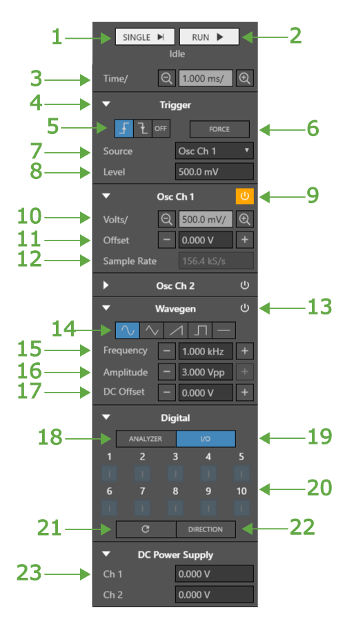
The instrument panel provides access to core device functionality and enables the user to configure the triggers, oscilloscope, wavegen, logic analyzer, gpio, and power supplies, manipulate the cart, acquire samples and more.
- Single - Perform a single-shot acquisition. Clicking this button will arm the trigger and return a single buffer of data once the acquisition completes.
- Run - Clicking this button will arm the trigger. When the acquisition completes and the device is in run mode a buffer of data is returned and the trigger is automatically re-armed.
- Time/ - The time per division of the chart's X-axis.
- Expand / Collapse - Click to expand or collapse the control panel section.
- Trigger Mode - The trigger mode. From left to right: Rising, Falling, Off.
- Force Trigger - If the trigger is armed this button forces the trigger condition and returns a buffer of data once the acquisition is complete. If the trigger is not armed this button has no effect.
- Source - The trigger source.
- Level - The trigger threshold level.
- Enable Button - Toggle the oscilloscope channel on / off.
- Volts/ - The volts per division on the Y-Axis of the chart.
Note: Each oscilloscope and logic analyzer channel has it's own independent Y axis.
- Offset - The Y-Axis offset of the specified channel.
- Sample Rate - The rate at which the oscilloscope channel will be sampled.
Note: This value is read only be default and is updated based on the chart zoom.
- Enable - Toggle the wavegen on/off.
- Wave Type - The regular waveform output type. From left to right: sine, triangle, sawtooth, square, dc.
- Frequecy - The frequency of the periodic regular waveform.
- Amplitude - The peak-to-peak amplitude of the waveform.
- DC Offset - The DC offset of the waveform.
- Analyzer - Select digital pins to use as logic analyzer inputs.
- I/O - Set output values of digital outputs and display input values of pins configured as digital inputs.
- Digital Channels - The digital channels.
- Digital channels configured as logic analyzer channels are indicated with a green background and A.
- Digital channels configured as inputs are indicated with a blue background and an I.
- Digital channels configured as outputs are indicated with a blue background, black outline, and an O.
- Digital inputs and output channels are dull when at a logic low value and bright when at a logic high value.
- Refresh - Read the digital input values and update the display.
- Direction - Set digital channel directions as input or output.
- Ch1 - DC Supply Channel 1 value.
Note: After setting a new value the actual achieved value will be displayed